IE340 Series Installation Guide
100
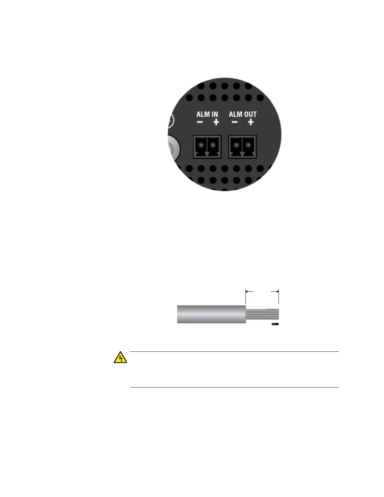
Before wiring an alarm connector, familiarize yourself with the negative
and positive polarities of its two pins by examining the legends on the top
panel. Refer to Figure 38.
Figure 38. Polarity Legend for the Alarm Connectors
The following procedure shows the ALM OUT connector. The procedure is
the same for the ALM IN connector. To wire an alarm connector, perform
the following procedure:
1. Strip 6.5mm (0.25 in.) of insulation from the ends of the wires with a
wire insulator stripper. Refer to Figure 39.
Figure 39. Stripping an Alarm Wire
Do not strip more than the recommended amount of wire. Stripping
more than the recommended amount can create a safety hazard by
leaving exposed wire on the terminal block after installation. E10
2. Tightly wrap the wire strands with your finger tips. Refer to Figure 40
on page 101.
This step is to prevent loose strands from touching other wires and
causing an electrical short.

 Loading...


