4. Configuration
95
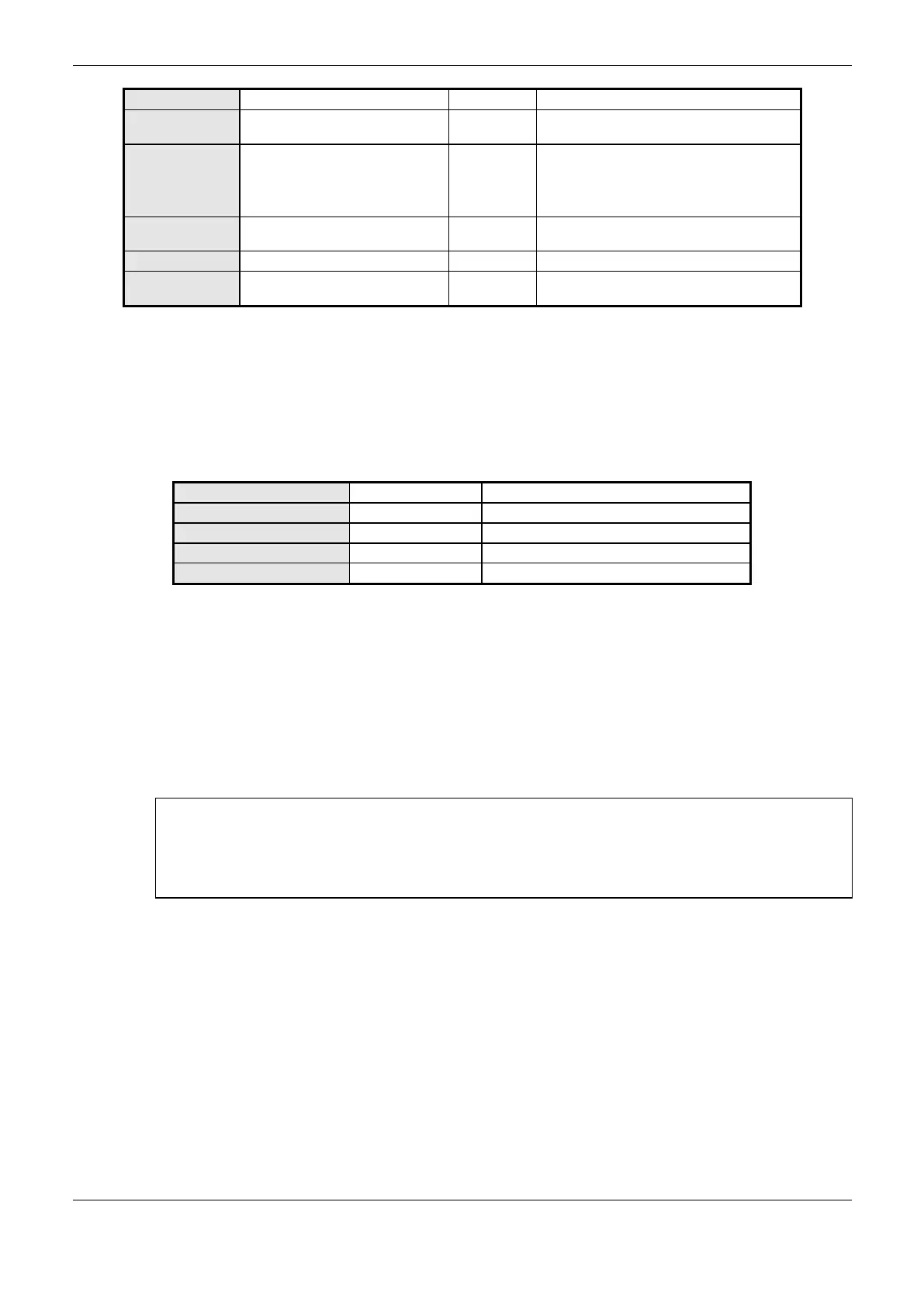
Name of a variable declared in a program or
GVL
Coil (1-bit)
Input Status (1-bit)
Holding Register (16-bit)
Input Register (16-bit)
MODBUS data initial address
The data address range
configured
Table 4-59. MODBUS Mappings Configurations
Notes:
Variable Value: this field is used to specify a symbolic variable in MODBUS relation.
Data Type: this field is used to specify the data type used in the MODBUS relation.
Digital output that can be read or written.
Digital input (read only).
Analog output that can be read or written.
Analog input (read only).
Table 4-60. Data types supported in MODBUS RTU Slave
Data Start Address: data initial address of the MODBUS relation.
Data Size: the Data Size value sets the maximum amount of data that a MODBUS relation can
access from the initial address. Thus, in order to read a continuous range of addresses, it is necessary
that all addresses are declared in a single relation. This field varies according to the configured type
of MODBUS data.
Data Range: this field shows the user the memory address range used by the MODBUS relation.
ATTENTION:
Differently from other application tasks, when a depuration mark in the MainTask is reached, the
task of a Slave MODBUS RTU instance and any other MODBUS task will stop running at the
moment that it tries to perform a writing in a memory area. It occurs in order to keep the consistency
of the memory areas data while a MainTask is not running.
MODBUS Slave Protocol Configuration via Direct Representation (%Q)
To configure this protocol using Direct Representation (%Q), you must perform the following steps:
Configure the general parameters of MODBUS slave protocol, such as: communication times,
address and direct representation variables (%Q) to receive diagnostics and control relations.
Add and configure MODBUS relations, specifying the MODBUS data type, direct representation
variables (%Q) to receive/write the data and amount of data to communicate.
The descriptions of each setting are listed below, in this chapter.
General Parameters of MODBUS Slave Protocol – Configuration via Direct Representation (%Q)
The general parameters, found on the home screen of MODBUS protocol configuration (Figure
4-25), are defined as:
 Loading...