4. Configuration
78
Configure the serial interface, choosing the transmission speed, the RTS/CTS signals behavior,
the parity, the channel stop bits, among others configurations by a double click on the COM 1 or
COM 2 serial channel.
See Configuration - Serial Interfaces Configuration chapter.
MODBUS Master Protocol Configuration by Symbolic Mapping
To configure this protocol using symbolic mapping, you must perform the following steps:
Configure the general parameters of the MODBUS Master protocol, like: transmission delay
times and minimum interframe as in Figure 4-14.
Add and configure devices via the General Parameters tab, defining the slave address,
communication time-out and number of communication retries as can be seen in Figure 4-15.
Add and configure the MODBUS mappings on Mappings tab as Figure 4-16, specifying the
variable name, data type, and the data initial address, the data size and range are filled
automatically.
Add and configure the MODBUS requests as presented in Figure 4-17, specifying the function,
the scan time of the request, the starting address (read/write), the data size (read/write) and
generate diagnostic variables and disabling the request via the buttons at the bottom of the
window.
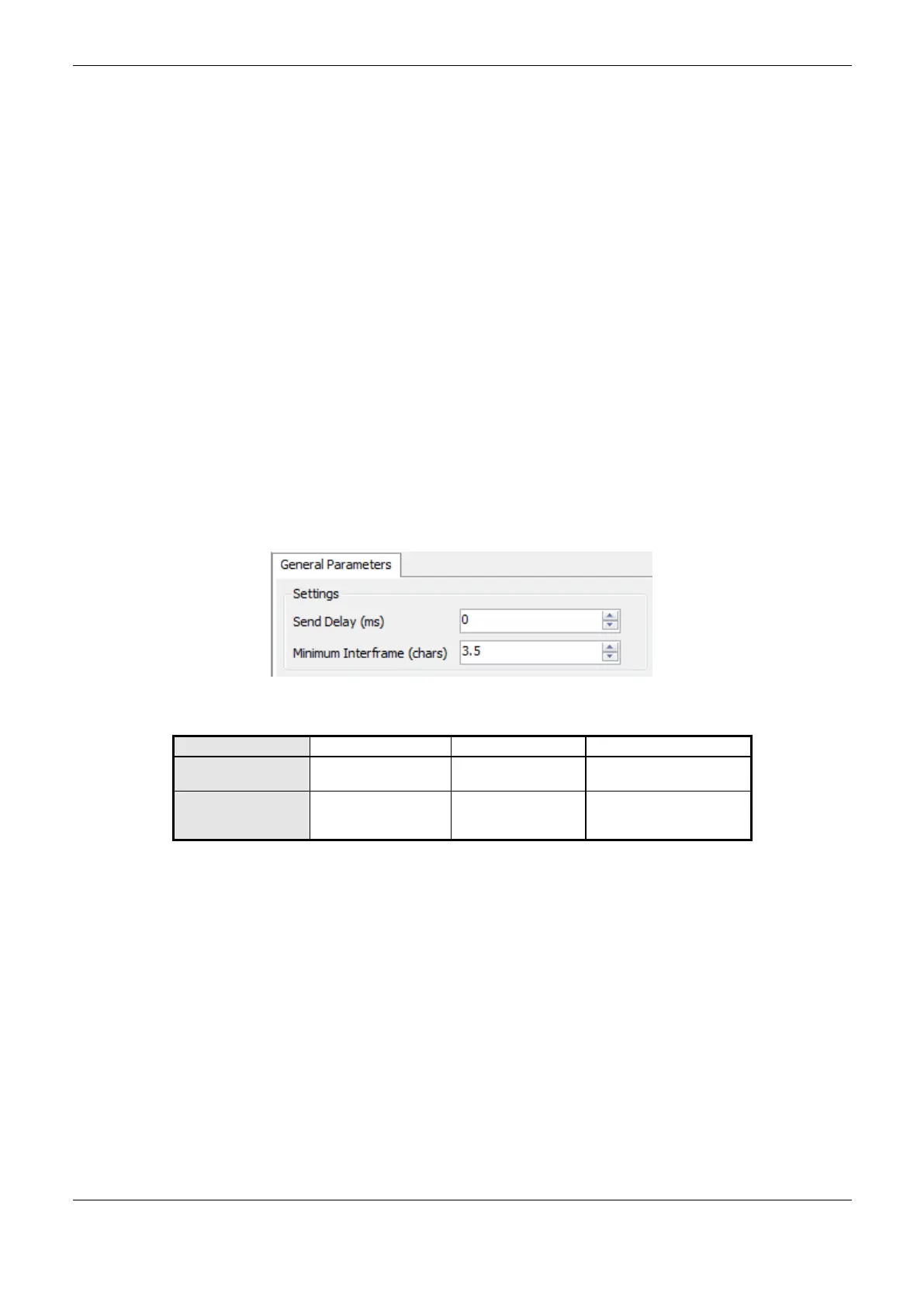
MODBUS Master Protocol General Parameters – Symbolic Mapping Configuration
The general parameters, found on the MODBUS protocol initial screen (Figure 4-14), are defined as:
Figure 4-14. MODBUS RTU Master Configuration Screen
Delay for the answer
transmission
Minimum
Interframe (chars)
Minimum silence time
between different
frames
Table 4-44. MODBUS RTU Master General Configurations
Notes:
Send Delay: The answer to a MODBUS protocol may cause problems in certain moments, as in the
RS-485 interface or other half-duplex. Sometimes there is a delay between the slave answer time and
the physical line silence (slave delay to put RTS in zero and put the RS-485 in high impedance state).
To solve this problem, the master can wait the determined time in this field before sending the new
request. Otherwise, the first bytes transmitted by the master could be lost.
Minimum Interframe: The MODBUS standard defines this time as 3.5 characters, but this
parameter is configurable in order to attend the devices which do not follow the standard.
The MODBUS protocol diagnostics and commands configured, either by symbolic mapping or direct
representation, are stored in T_DIAG_MODBUS_RTU_MASTER_1 variables. For the direct
representation mapping, they are also in 4 bytes and 8 words which are described in Table 4-45
(where “n” is the configured value in the %Q Initial Address of Diagnostic Area field).
 Loading...