4. Configuration
82
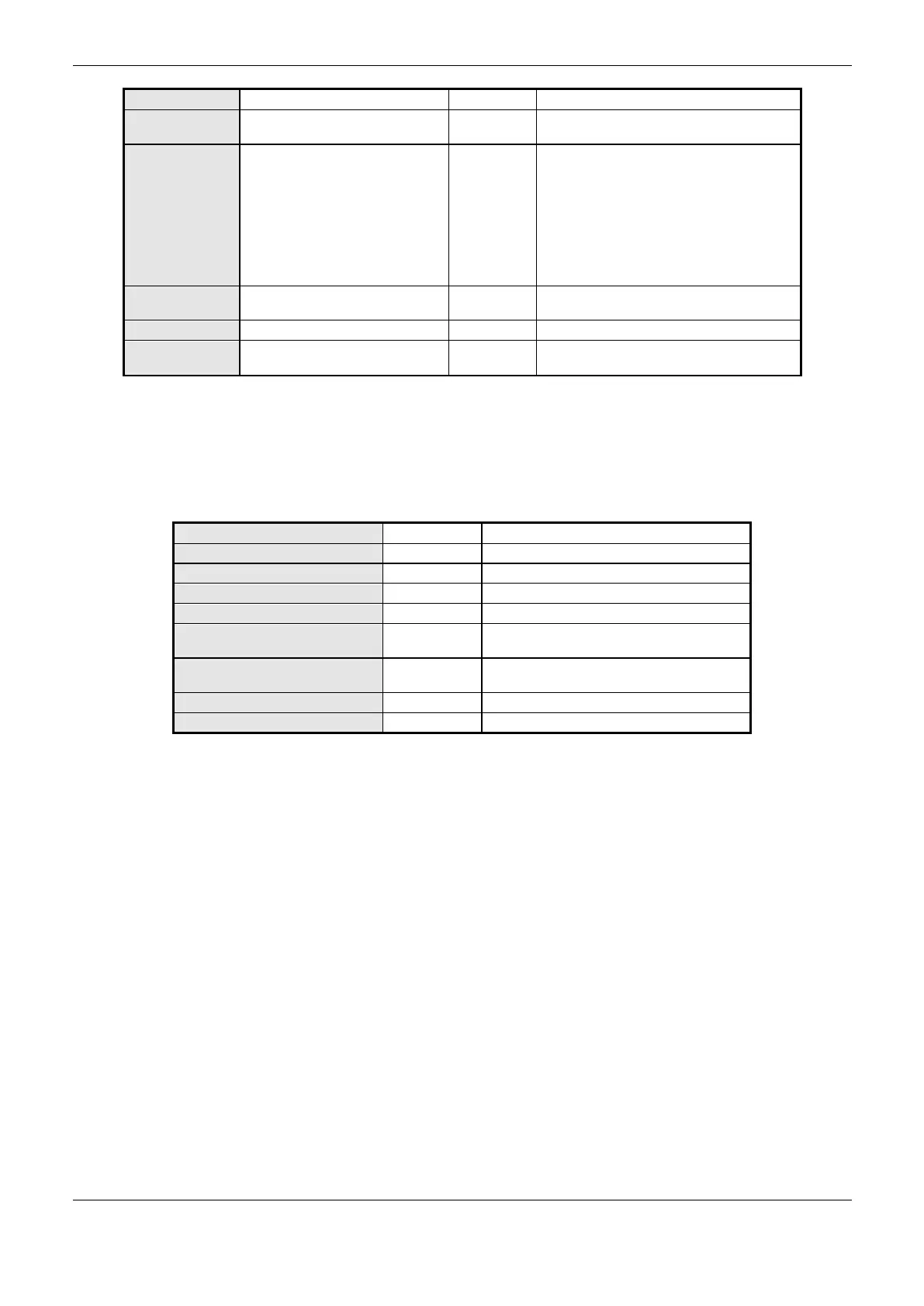
Name of a variable declared in a program or
GVL
Write Coil (1 bit)
Read Coil (1 bit)
Write Holding Register (16 bits)
Read Holding Register (16 bits)
Holding Register – AND Mask (16 bits)
Holding Register – OR Mask (16 bits)
Input Register (16 bits)
Input Status (1 bit)
Initial address of the MODBUS
data
The address range of configured
data
Table 4-47. MODBUS Mappings Settings
Notes:
Value Variable: this field is used to specify a symbolic variable in MODBUS relation.
Data type: this field is used to specify the data type used in the MODBUS relation.
Holding Register with AND mask
Analog output which can be read or written
with AND mask.
Holding Register with OR mask
Analog output which can be read or written
with OR mask.
Analog input which can be only read.
Digital input which can be only read.
Table 4-48. Data Types Supported in MODBUS RTU Master
Data Initial Address: data initial address of a MODBUS mapping.
Data Size: the size value specifies the maximum amount of data that a MODBUS interface can
access, from the initial address. Thus, to read a continuous address range, it is necessary that all
addresses are declared in a single interface. This field varies with the MODBUS data type
configured.
Data Range: this field shows the user the memory address range used by the MODBUS interface.
Requests Configuration –Symbolic Mapping Settings
The configuration of the MODBUS requests, viewed in Figure 4-17, follow the parameters described
in Table 4-49:
 Loading...