PN 305892901, Rev S
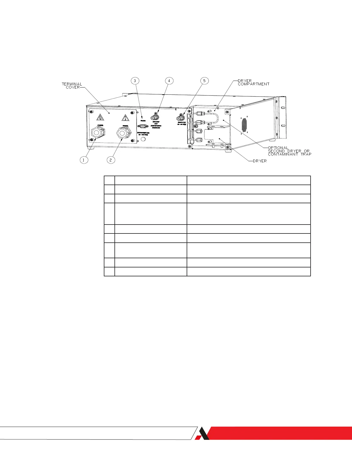
Figure 2-2.
3050-RM rear panel
connections and inside of
dryer compartment.
Rear Panel Connections and Interface Board
See Figures 2-2 and 2-3 for location of analyzer connections on the Rear Panel
and Interface board. Remove Terminal Cover to access Interface board.
Item Function
1 Power Conduit Cable gland for analyzer power cord.
2 Signal Conduit Cable gland for signal connections
3 RS-232 Serial Port User serial communications interface. Serial wiring
supplied by user. Observe caution regarding use in
hazardous locations.
4 Exhaust Fitting Vent port for cell exhaust; 1/8-inch compression tting.
5 Sample Inlet Fitting Input port for sample gas; 1/8-inch compression tting.
6 Power connector Connect hot (1) and neutral (2) to power connector
and ground to chassis.
7 Fuse Receptacle 2 A, 250 V, time lag, T-type.
8 Line Voltage Selector Select 120 Volt or 240 Volt line voltage.
Installation and Start-Up | 2-7

 Loading...


