PN 305892901, Rev S
Gas Connections
Install a main process shut-o valve and pressure regulator (recommended) at
the sample tap. Locate the analyzer as close as possible to the sample source.
The amount of time that the analyzer gas ttings are left open should
be kept to less than one (1) minute.
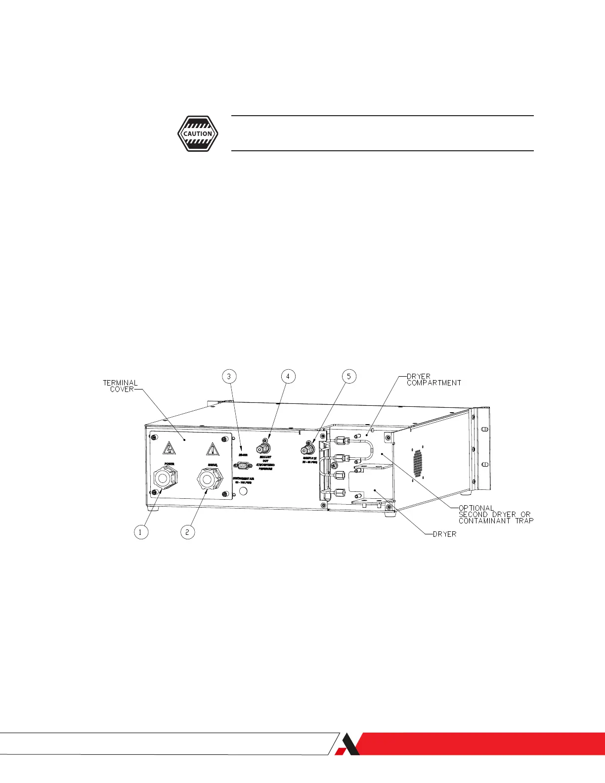
To make the gas connections (refer to Item numbers in Figure 2-5):
1. Remove the Swagelok caps from the Sample Inlet tting (Item 5) and
Exhaust Outlet tting (Item 4). Keep the tting caps. If you have to ship
the analyzer or if it has to be disconnected for an extended period of time,
reinstall the caps.
2. Connect the Sample Inlet tube to the analyzer Sample Inlet.
3. Connect the exhaust tube to the analyzer Exhaust Outlet. The exhaust
must be vented to an appropriate vent system.
4. Check all Sample Inlet and Exhaust Outlet ttings for leaks.
Figure 2-5.
3050-RM rear panel gas
connections.
Installation and Start-Up | 2-11

 Loading...


