PN 305892901, Rev S
ON
ON
TB3
TB2
TB1
ANALOG
OUTPUT
DATA
VALID
CONC
ALARM
SYSTEM
ALARM
OUT
- + IN
RD TD
+ - + -
LINE VOLTAGE
FUSE
L N G
1 2 3
RS-485
TERMINATOR
1 2 3 4 5 6 7 8 9 10 11 12 13 14
115
230
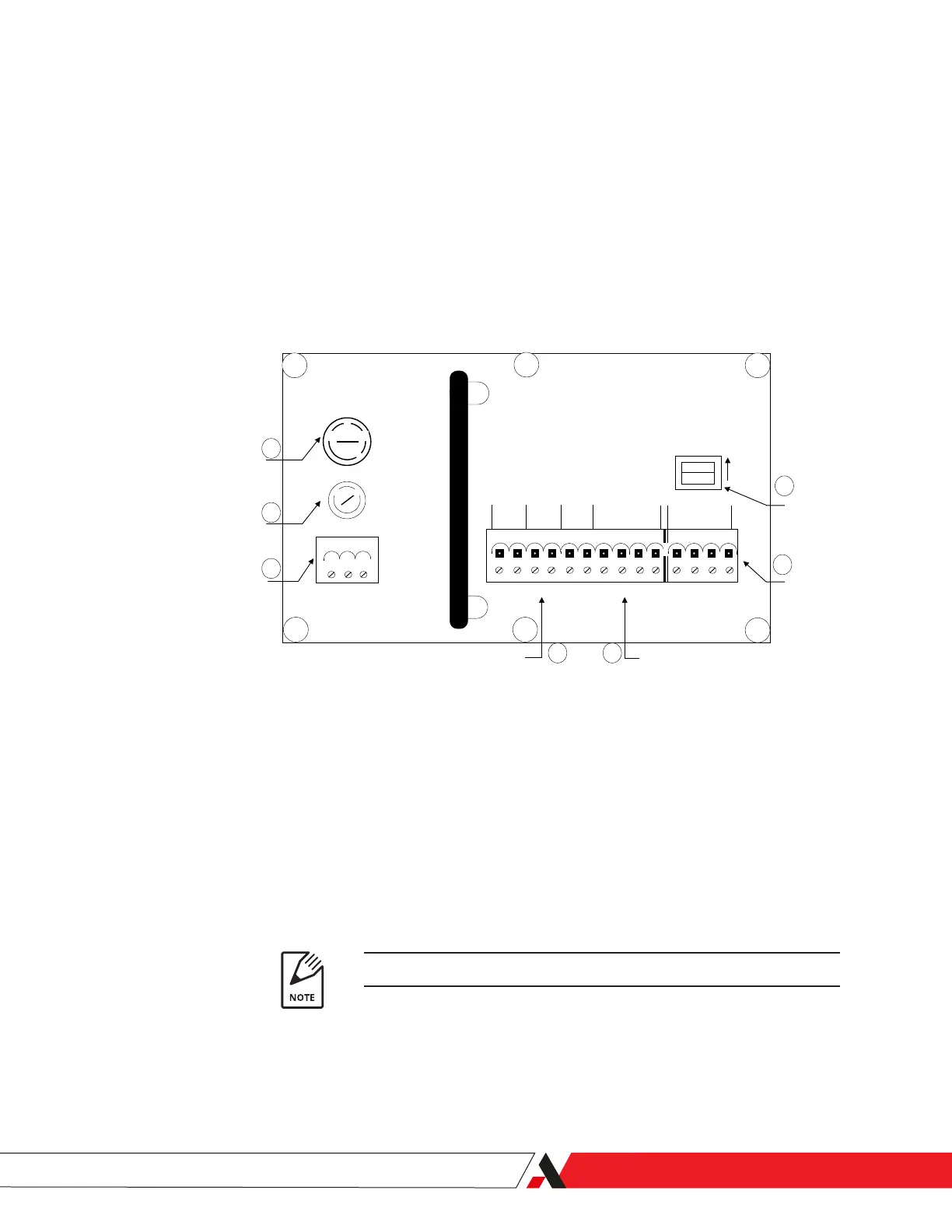
Line Voltage Selector
Fuse Receptacle
Power Connector
Alarm & Alert Contacts Analog Output
RS-485
Serial Port
RS-485
Terminator
10
9
8
14 13
12
11
Figure 2-9.
Communication connections
on the 3050-RM Analyzer
Interface board.
Communication Connections
To make the communication connections (refer to Item numbers in Figures 2-9
and 2-2):
1. Disconnect the power from the analyzer and remove the Terminal Cover
from the Rear Panel.
2. Connect the 4–20 mA analog output (Item 13) (see also Figures 2-10.1 and
2-10.2) and Conc Alarm and Data Valid terminals (Item 14) on the Interface
board to the analyzer through the metallic Signal conduit (Item2, Figure
2-2).
3. Connect the RS-232 or RS-485 serial communication to the analyzer. The
RS-485 connection, analog output, and Conc Alarm/Data Valid contacts
share the same cable.
4. If using RS-485 communications, turn on the RS-485 Terminator switch
(Item 11) if communicating with one analyzer or the last in a chain of ana-
lyzers.
2-wire and 4-wire mode selection is performed using software.
5. Replace Terminal Cover.
Installation and Start-Up | 2-15

 Loading...


