PN 305892901, Rev S
Power Connection
If the factory-supplied exible power cord is not long enough or is not compli-
ant with local standards, a 3-meter European-type harmonized power cord is
also included.
Ensure that the area is safe and replace the power cord as follows:
1. Disconnect the power from the analyzer and remove the Terminal Cover
from the Rear Panel.
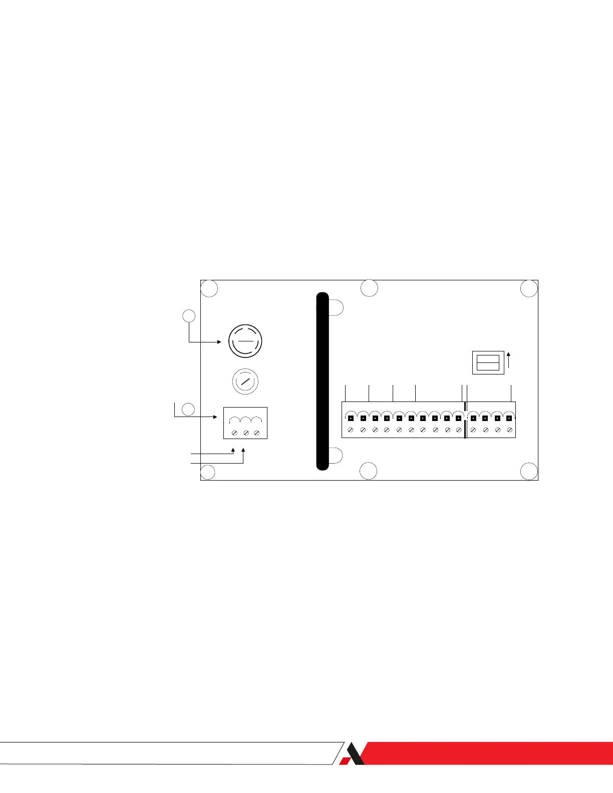
2. Unplug the power connector (Item 8, Figure 2-7) and unscrew the two (2)
plug screws that secure the “1” (LINE) and “2” (NEUTRAL) wires in place.
3. Remove the ground wire from the threaded chassis Ground Stud (Figure
2-8).
ON
ON
TB3
TB2
TB1
ANALOG
OUTPUT
DATA
VALID
CONC
ALARM
SYSTEM
ALARM
OUT
- +
IN
RD TD
+ - + -
LINE VOLTAGE
FUSE
L N G
1 2 3
RS-485
TERMINATOR
1 2 3 4 5 6 7 8 9 10 11 12 13 14
115
230
1 (L) (LINE)
2 (N) (NEUTRAL)
POWER
CONNECTOR
10
8
Figure 2-7.
Remove 1 (L) and 2 (N).
4. Loosen and remove the power cord strain relief cap with compression
bushing (Item 1 in Figure 2-2) and pull out the power cord.
5. Prepare the new power cord using the original cord as a guide:
a. Remove the outer jacket.
b. Measure the length of the wires.
c. Strip lengths of wires.
d. Ring connector termination, etc.
Installation and Start-Up | 2-13

 Loading...


