Analog Interface Board
The Analog Interface board (AMETEK Part No. 591144901) is located on top of
the MCU board at the front of the Electronics Module (Figures 4-9 and 4-10).
Removing the Analog Interface Board
• Remove the four (4) knurled screws that secure the board in place. One (1)
of the screws secures the PSV board in place. Remove as described above.
• Unplug the connectors attached to the Analog Interface board (Figures
4-9 and 4-10).
• Carefully, lift the board until it slides free of the connector.
Replacing the Analog Interface Board
• Position the new Analog Interface board on the connector and press
rmly to insert.
• Replace the screws removed earlier. Do not overtighten.
• Plug in the Analog Interface board connectors.
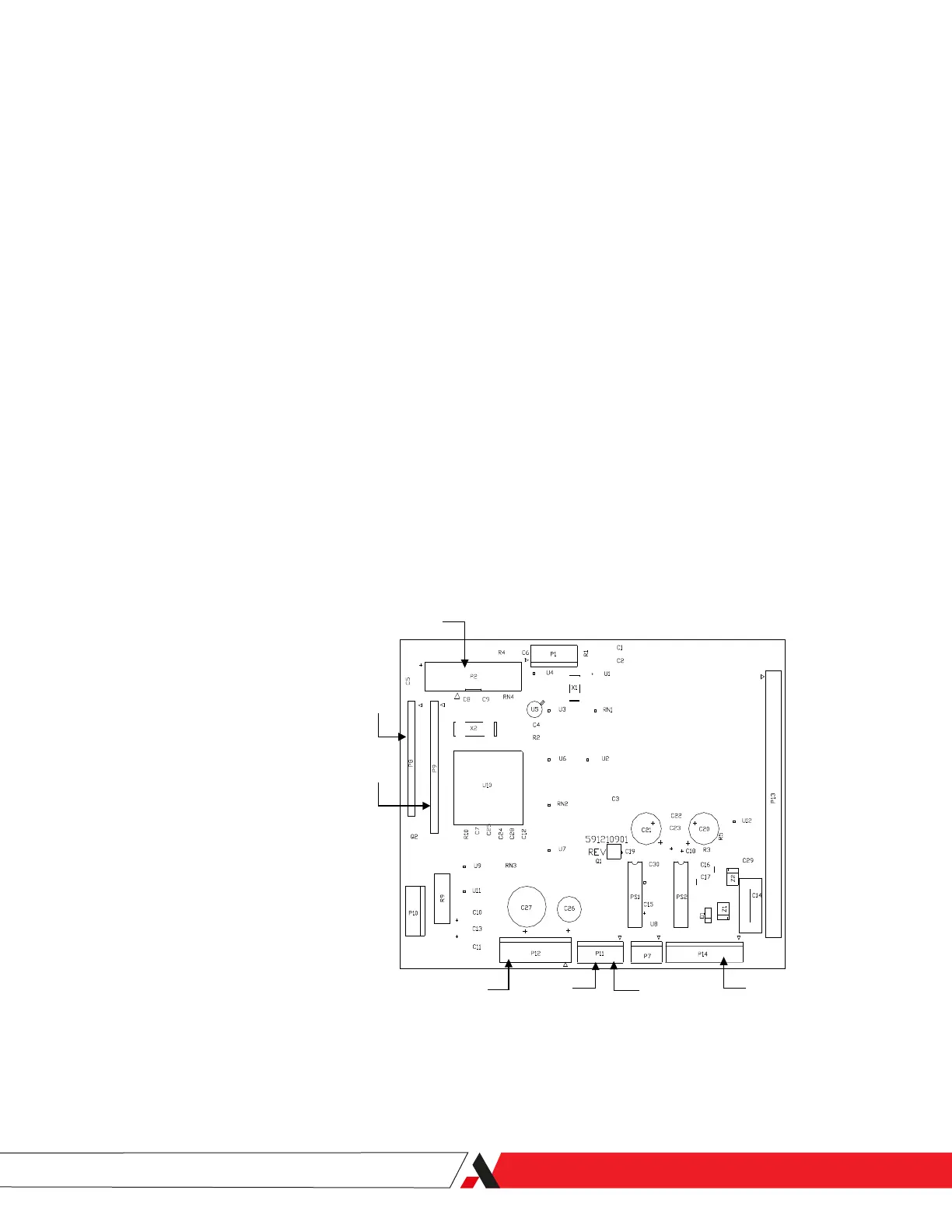
Sensor
LCD Display
Front Panel
DC Power
Fan
(Single)
Fan
(Dual)
System Alarm
P1 Thermistor
P2 Sensor
P8 LCD Display
P9 Front Panel
P11 Single Fan and Dual Fan
P12 DC Power
P14 System Alarm
Figure 4-10.
Analog Interface board
connections.
PN 305892901, Rev S
Maintenance and Troublshooting | 4-19

 Loading...


