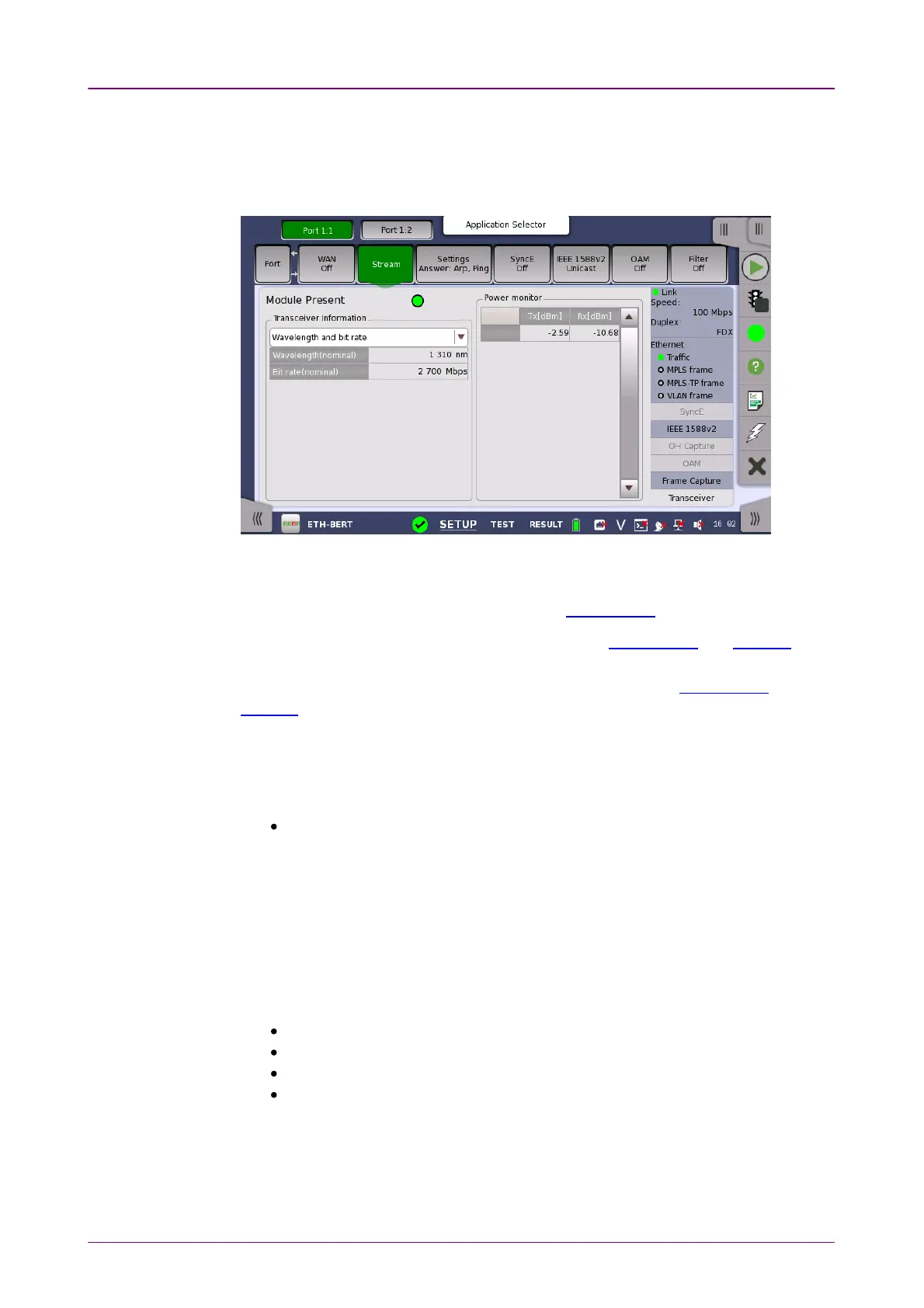
Module PresentModule Present
TransceiverTransceiver
InformationInformation
66..11..33..99 TransceiverTransceiver
Touching the TransceiverTransceiver button in the status area of the Ports SetupPorts Setup screen
displays the status shown below.
This screen presents status information about the optical transceiver (Pluggable
module installed on the connector panel).
When the optical transceiver is SFP or SFP+, I2C analysisI2C analysis appears.
When the optical transceiver is QSFP+ or QSFP28, I2C analysisI2C analysis and SettingsSettings
appear.
When the optical transceiver is QSFP56, QSFP-DD, or OSFP, I2C analysisI2C analysis and
SettingsSettings appear.
GreenGreen indicates that an optical transceiver is currently mounted.
Select the information from pull down menu. AlarmAlarm and Output controlOutput control appear
when the bit rate is 40 Gbps or greater.
AlarmAlarm shows the alarm status.
Loss of Signal: Turns on red when no optical signal is detected.
Configuration alarm: Indicates the status of Configuration Error Code register
in the optical transceiver.
Gray: No Status
Green: Config accepted
Red: Config rejected
Temperature alarm: Appears if the optical transceiver is QFP-DD. Turns on
red when the temperature alarm of the optical transceiver raises.
Wavelength and bit rateWavelength and bit rate shows the nominal wavelength and bit rate.
ComplianceCompliance shows the available standards.
Vendor informationVendor information shows the data stored in the optical transceiver.
Output controlOutput control allows to select lanes to insert alarm/errors.
Tune wavelengthTune wavelength
When the optical transceiver is a tunable SFP, the following items are displayed
for Wavelength and bit rateWavelength and bit rate.
Bit rate, Channel, Wavelength, Frequency, First frequency, Last frequency,