5.2 Measuring Optical Transceiver Module
5-5
5
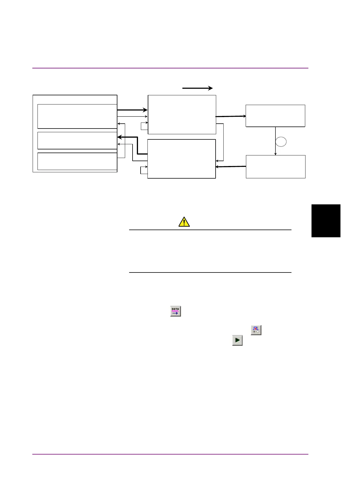
Figure 5.2-1 Connection diagram for Optical module evaluation
9. Turn on the MP1862A, DUT, MP1861A and MP1800A in order.
CAUTION
The DUT may be damaged if a signal line is connected or
disconnected while the output is ON. Be sure to turn off
the MP1800A and MP1861A before changing the cable
connection.
10. On the
tab of MP1861A, select
in the
box.
11. Turn on the output from MP1861A by clicking the
module
function button (
) or pressing the
key on the front panel
of MP1800A.
12. Click the
module function button ( ).
13. Click the
module function button ( ).
14. On the
tab of MP1862A, check the measurement results.
15. On the
tab of MP1861A, measure the sensitivity of
the DUT (E/O), changing the values in the
and
boxes.
MP1800A
MU183020A
Ext Clock Input
Clock Output
MU183040B
Ext Clock Input
MU181000A Clock Output
MP1861A
Data Output1/2
Data Input1/2
Data Input1/2
Ext Clk Input
Data Output
Mux Clk Input
Delayed Clk Output
Clk Output1/2
被測定物(E/O 素子
EMLなど)
MP1862A
Data Output1/2
½ Clk Output
Data InputDemux Clk Input
Delayed Clk Output
Ext Clk Input
被測定物(E/O 素子
PIN-DIODEなど)
Optical Fiber
32G Data×2
DUT
(E/O device, EML, etc.)
(O/E device, PIN-diode,