4.4 Setting Input Interface
4-15
4
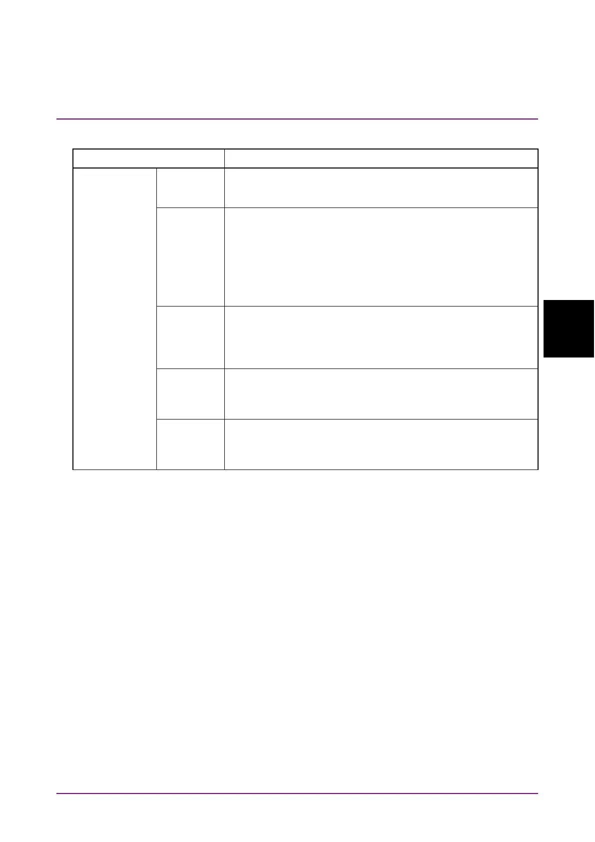
Table 4.4.1-4 Composition of Clock Input Setting Screen (Cont’d)
Setting items Setting items
Sets a delay in the range of –1000 to 1000 mUI, in 4 mUI steps.
This module operates based on UI units. Increasing the numeric
value increases the delay.
Sets a delay in steps of ps units, equivalent to 4 mUI. The setting
range is the equivalent to the range of
–
1000 to 1000 mUI that is
converted into ps units.
64 GHz: –15.6 to 15.6 ps
56 GHz: –17.8 to 17.8 ps
25 GHz: –40 to 40 ps
When the red frequency counter value range is incorrect, “----” is
Clicking Calibration executes self calibration. When the alarm
indicator on the button is red, calibration should be performed.
Sometimes, the delay time may be changed greatly by executing
calibration, so take care when performing calibration during
Clicking Relative sets the current delay in 4-mUI steps relative
to the reference value of 0 mUI. When
is clicked again,
the setting is converted from the relative value to the current
Sets whether to input jitter.
To perform jitter tolerance test while inputting jitter-modulation
applied clock, this button must be ON. Refer to 4.4.2 “When
inputting jitter-modulated signals” for details.
Notes:
•
When the frequency or the temperature condition is changed,
the alarm indicator on
lights, prompting
performance of calibration. If calibration is not performed at
this time, the error in the phase setting may be greater than at
a normal phase setting.
•
Values displayed in ps units vary as the frequency changes,
because the MP1862A sets phases in mUI units as an internal
standard.
•
The phase setting accuracy varies depending on the option
selected in the
box of the
tab for
MU183040A/B. If
is selected, the phase setting accuracy
becomes lower than that of when
is selected.