Chapter 2 Preparation
2-14
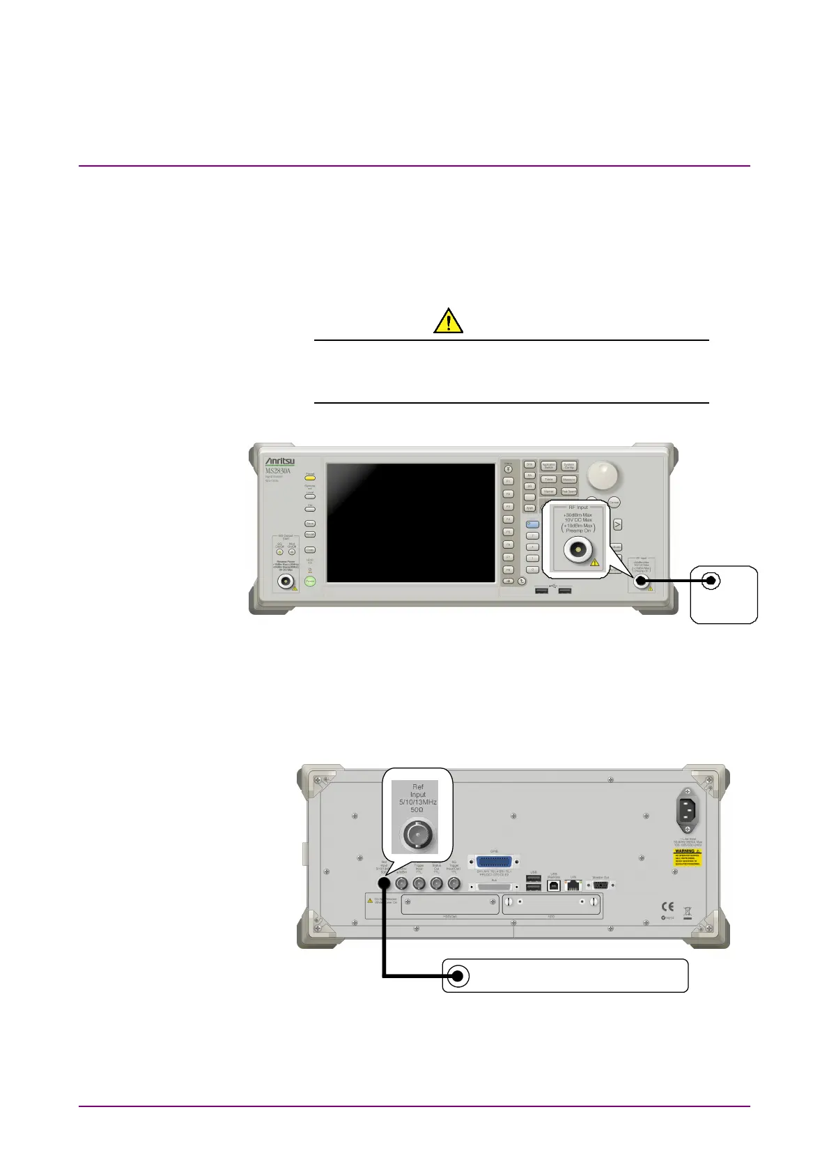
2.2 Signal Path Setup
As shown in Figure 2.2-1, connect the mainframe and the DUT using an
RF cable, so that the signal to be tested is input to the RF Input
connector.
CAUTION
Do not input a signal that has an excessive level to
MS2830A, MS2840A.
DUT
Figure 2.2-1 Signal path setup example
Set the 5 MHz/10 MHz/13 MHz reference signal from external sources, as
required.
Reference frequency signal
Figure 2.2-2 External signal input