Chapter 3 Measurement
3-100
3.9.8 RF Signal Generator window
This section describes the display of RF signal settings output to DUT in
the RF Signal Generator window.
Figure 3.2.1.5-1 Audio Analyzer + RF Signal Generator Screen
In the RF Signal Generator window, the display can be changed and the
parameters can be set by using the rotary knob, Cursor key, Enter key,
and Cancel key.
Note:
Press to select a parameter. Press to deselect the selected
parameter.
[1]
[2] [5]
[4]
[3]
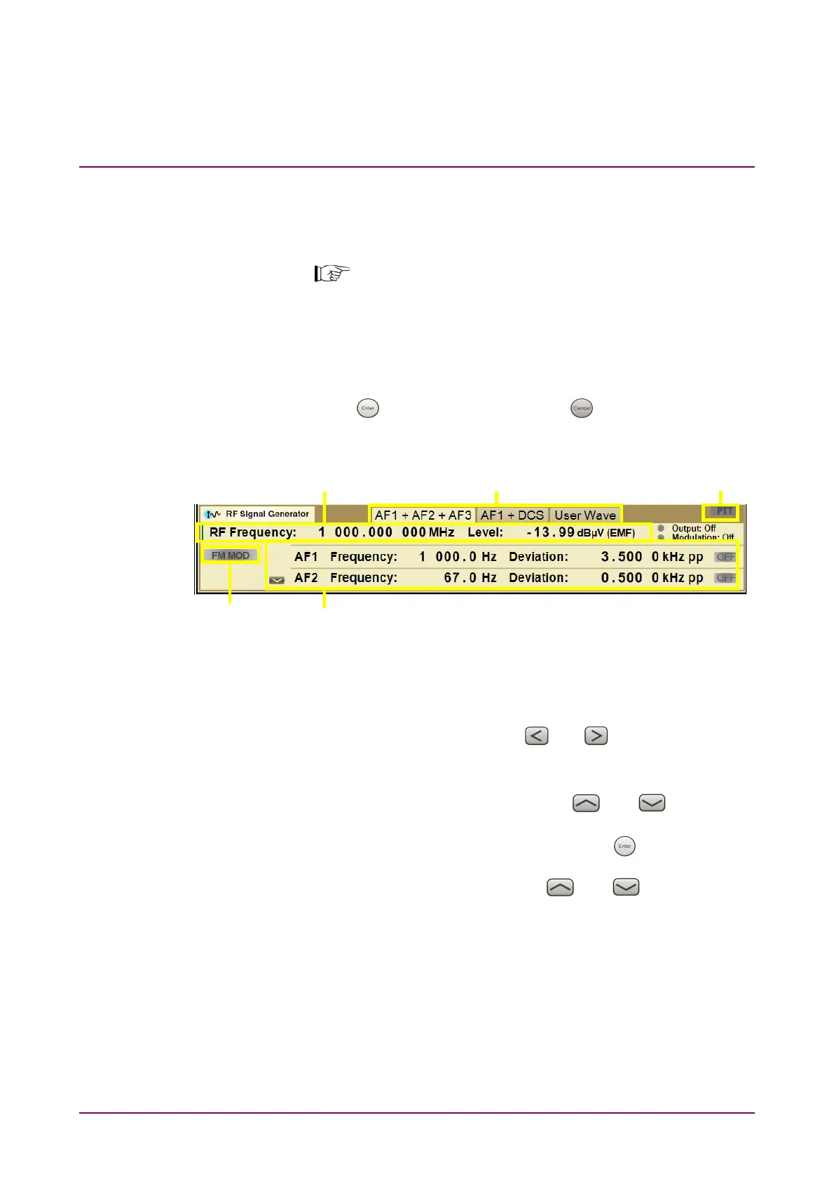
Figure 3.9.8-1 RF Signal Generator Window
(RF Signal Setting Mode, No parameter is selected)
[1] AF signal type
Selects AF signal type by using
and . The selected AF
signal type is highlighted and the parameters are displayed in [3].
[2] Setting RF signal
Selects RF signal setting mode by using
and . When the
green line is displayed at the left of RF Frequency as in Figure
3.9.8-1, RF signal setting mode is active. Press
to set the window
to parameter selection state, which allows frequency and level
settings by using the rotary knob or
and .