iHP Manual 11 | P a g e
The simplest way to get started is to use the Power Pro Connect Module (PPCM) to establish a link to the
supply. The PPCM allows the user to quickly establish a connection with the power supply with a Web based
GUI and set up the power supply. The configuration of the supply can be set up to run autonomously when
powered on, controlled via rear panel digital and analog input and outputs, or actively controlled via the
PPCM.
For more advanced users developing their own software control, the PPCM is not required and the supply can
be directly interfaced via the users preferred standard communications protocols, including CANbus, Ethernet
and RS485.
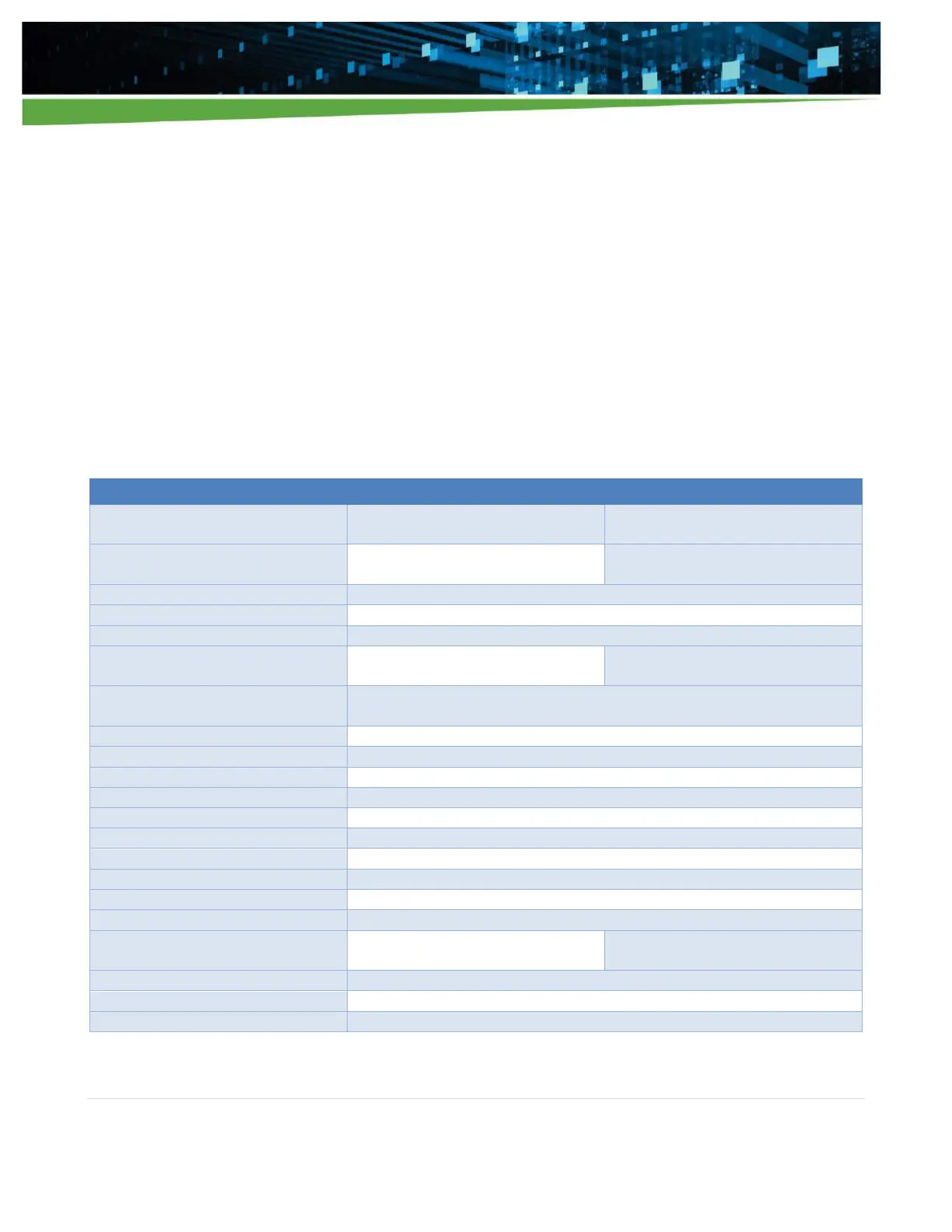
1.3 Specification Summary
Tables 1-1 and Table 1-2 below summarize the 24K and 12K input parameters, followed by Table 1-3 outlining
the general Module specifications
Table 1-1
iHP24 Electrical Specifications
19” Rack 24 KW strapped as 3-phase
380/480 Vac Nominal (iHP24H3A/L)
19” Rack 24 KW strapped as 3-phase
208/240 Vac Nominal (iHP24L3A/L)
342 Vac to 528 Vac
(Nominal rating 380/480 Vac)
187.5 Vac to 264 Vac
(Nominal rating 208/240 Vac)
3-phase (Wye or Delta) 4 wire total (3-phase and 1 protective earth ground)
Loss of phase will inhibit unit off. Housekeeping/comms must continue with phase loss.
51 A @ 342 Vac
40 A @ 432 Vac
Nominal input locked on at turn-on. Under voltage shutdown at 15% below nominal.
Turn-on at 12% below nominal. Not to interfere with SEMI F47 specs.
> 0.98 @ full load and nominal line
THD < 13%, PWHD < 22% (refer to EN 61000-3-12)
Designed to meet SEMI F47-0706, 53, 58, S14 at nominal input voltages
< 2.5 mA (Note for fixed condition 3rd edition leakage = 5 mA)
Front panel power switch provided
Internal fuse (not user serviceable)
Input overvoltage protection
Up to 115% of nominal input shall not damage unit
> 90% @ 3P 380 Vac full load
> 91% @ 3P 480 Vac full load
> 90% @ 3P 208 Vac full load
> 91% @ 3P 240 Vac full load