iHP Manual 56 | P a g e
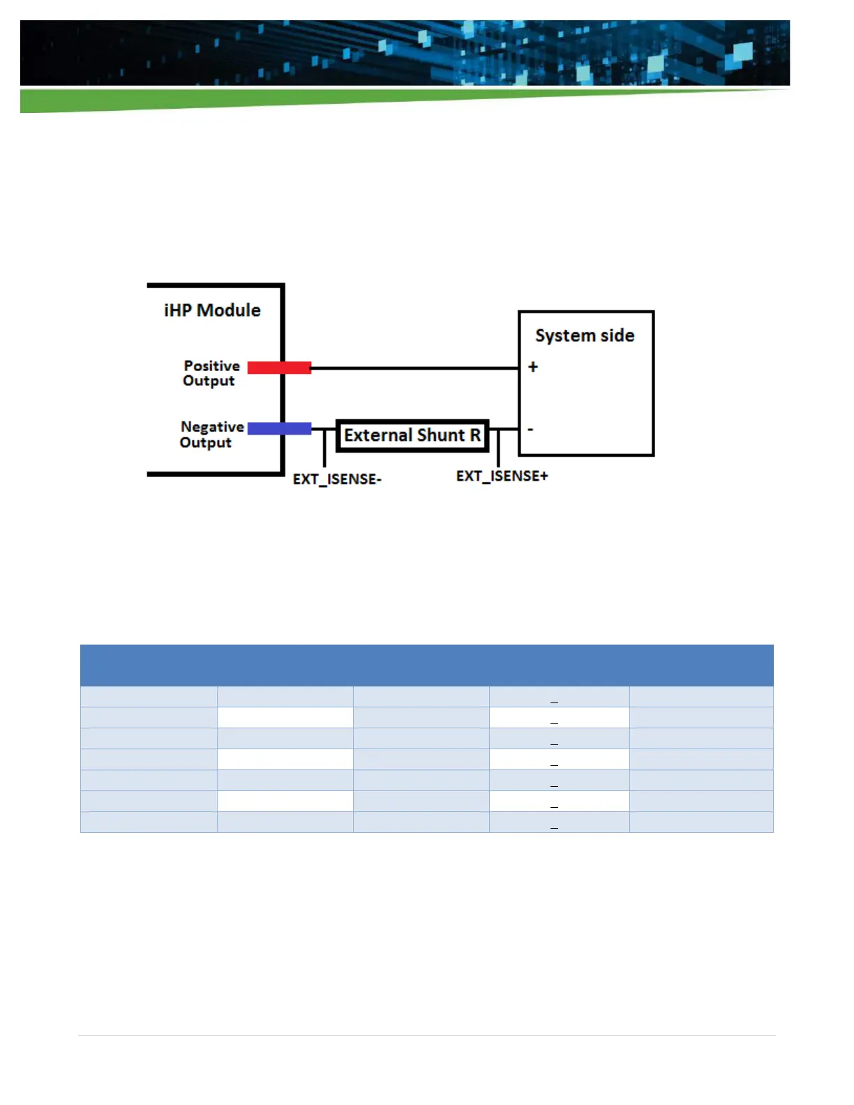
When using external current sense, all output current information used by the iHP module will be taken from
the differential voltage across the external shunt. The information collected from external sense connections
will be used for output reporting, current protection, and constant current operation.
Connection of the external shunt should only be on the negative output busbar of the iHP module. The
EXT_ISENSE- should be connected to the external shunt’s negative output busbar side and the EXT_ISENSE+
should be connected to the external shunt’s load side as shown in Figure 4-8.
Figure 4-8 Location of external shunt and external shunt sense lines
Table 4-9 list the required shunt resistor per iHP module.
Table 4-9
Module Current
Rating (A)
4.2.1.2.3 Current Monitor (IMON)
IMON J2 Pin 5 is an output signal. IMON functions as the current monitor signal of the module. It reports the
sensed output current with a scaled voltage between 0 and 10V according to Table 4-10. D_RTN J2 Pin2 is
used for twisted pair cabling with IMON.