iHP Manual 64 | P a g e
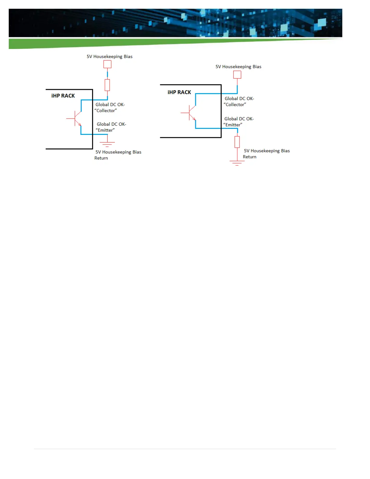
Figure 4-13 Possible circuits configuration for DCOK functionality
At iHP rack start-up, the iHP rack will detect the slots with populated modules. The assertion of hardware
DCOK signal will be based on the output status of the modules detected by the iHP rack during start-up. For
example:
When seven modules inserted to the iHP rack,
For the iHP rack DCOK signal to assert, all seven modules should have a power good status.
If any module has a power bad status, the iHP rack DCOK signal will be de-asserted.
When three modules inserted to iHP rack,
For the iHP rack DCOK signal to assert, all three modules should have a power good status.
If any module has a power bad status, the iHP rack DCOK signal will be de-asserted.
4.3 Module Operating Mode
The iHP modules can be operated in several operating modes. The operating mode is set by the ISOCOMM
D3h command and once set remains in the mode chosen until changed by a sending a new configuration via
the ISOCOMM D3h command.
Digital Voltage Source (DVS) – The module operates as a voltage source. The module output voltage
functions can only be controlled by sending a command using a PC or laptop.
Digital Current Source (DCS) – The module operates as a current source. The module output current
functions can only be controlled by sending a command using a PC or laptop.
Analog Voltage Source (AVS) – The module operates as a voltage source. The module output voltage can
only be controlled by inputting 0V-10V to module’s 0-10VEXT_VPROG signal (module J1 connector pin1) or
0V-5V to module’s 0-5VEXT_VPROG signal (module J1 connector pin2).