iHP Manual 47 | P a g e
4.2.1 Module Interface Signals
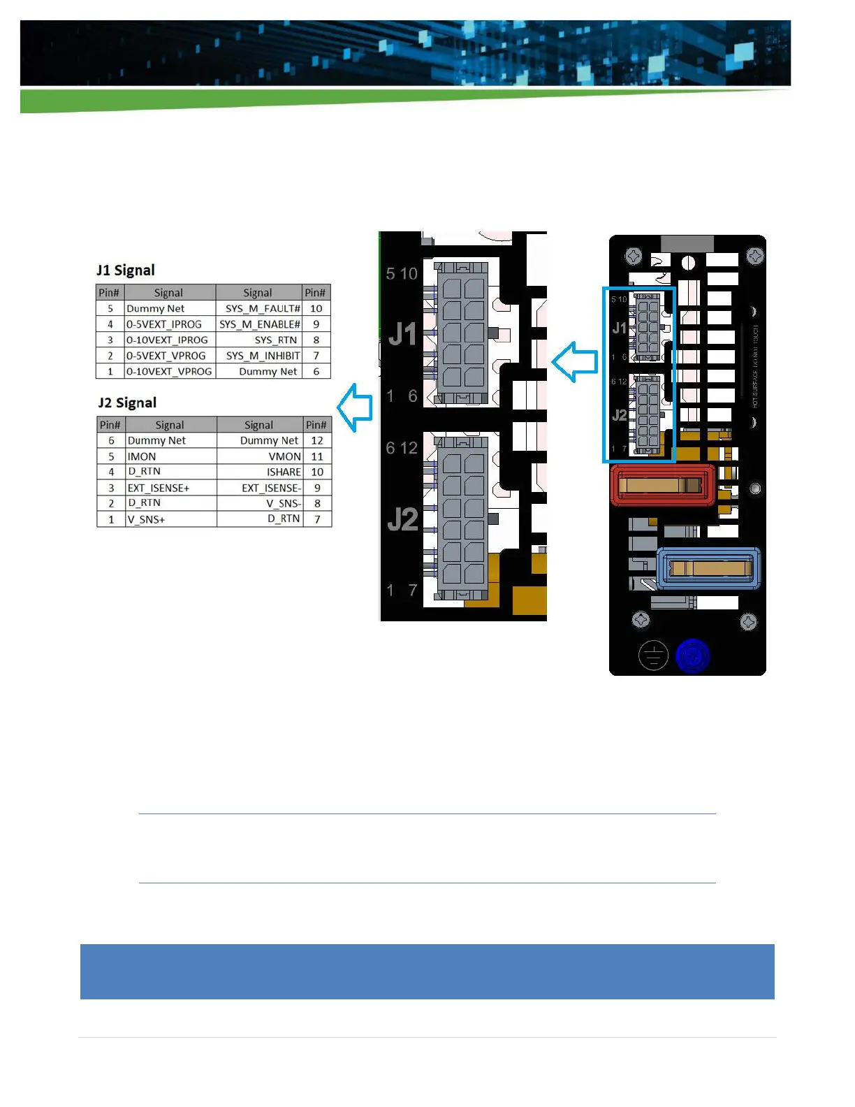
Figure 4-3 shows the location of the J1 and J2 connectors and the pin location of the signals. These signals
allow direct interface with the supply to allow direct control and monitoring of the iHP system using analog
and digital input and outputs.
Figure 4-3 Module J1 and J2 signal connections for controlling the modules
4.2.1.1 Module’s J1 Signal
Table 4-3 lists the signal information available on connector J1.
Warning! - The module’s J2 signals and output voltage are isolated from module’s J1
signals. D_RTN and SYS_RTN are completely isolated.
Table 4-3