iHP Manual 92 | P a g e
Ambient temperature monitoring is located on the front panel of iHP rack.
Once Ambient OTP is triggered, status will be reflected on the ISOCOMM command 7Dh
(STATUS_TEMPERATURE).
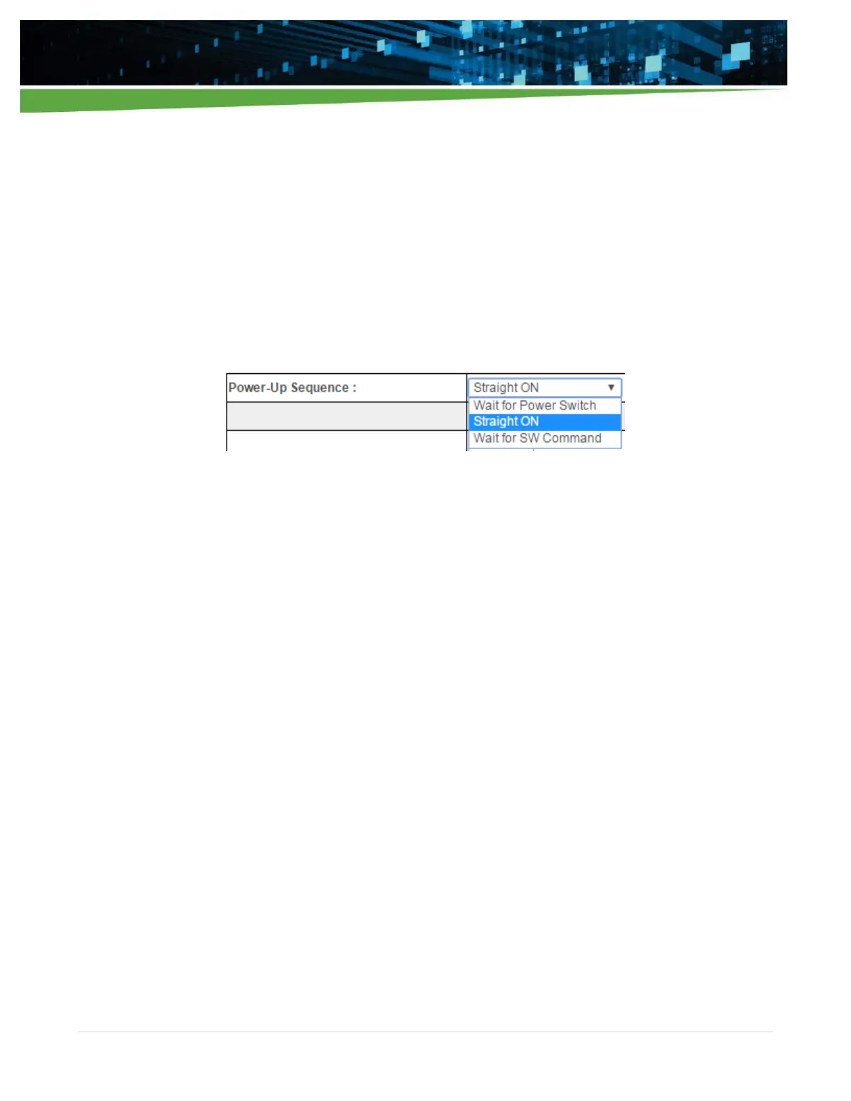
5.1.3.2 Power-Up Sequence
This configuration discusses the output status (on or off) during iHP power-up.
Power-up sequence can be configured as:
Wait for Power Switch
Straight ON
Wait for SW Command
Wait for Power Switch
Power Switch is located on the front panel of the iHP unit.
After turning-on the Input AC and ISOCOMM finishes its bootload process, modules will not turn-on.
Module will turn-on after pressing the Power Switch.
Power Switch will be operational after 20 seconds from the application of input AC.
Straight ON
After turning-on the Input AC and ISOCOMM finishes its bootload process, modules will turn-on
automatically.
Wait for SW Command
After turning-on the Input AC and ISOCOMM finishes its bootload process, modules will not turn-on.
User needs to send turn-on command via SW.
Send ISOCOMM Command: 10h Write_Protect Command; Data: 00h Command to disable
ISOCOMM write protect.
Send ISOCOMM Command: 01h Operational Command; Data: 80h Command to turn on the
module.
Note: Module turn-on will still be dependent on hardware inhibit or enable signals of iHP rack or iHP module.
5.1.3.3 INH0/EN0 TTL and INH1/EN1 TTL Function
This configuration allows the user to configure:
INH0/EN0 TTL signal (iHP Rack DSUB9 pin 5) as Inhibit Low or Enable Low function.
INH1/EN1 TTL signal (iHP Rack DSUB9 pin 4) as Inhibit High or Enable High function.