iHP Manual 21 | P a g e
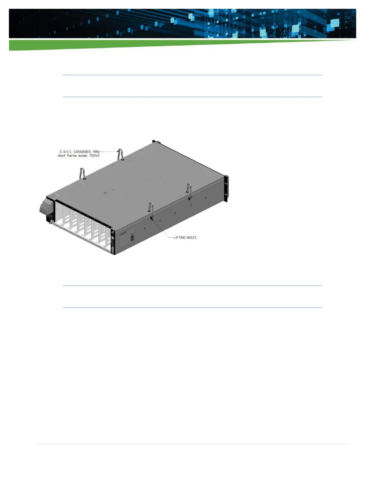
2.3.2 Lifting Provision
Warning! - 24KW iHP models require a minimum two-man lift.
The iHP rack has been provided with lifting holes which can accommodate carabiners. Recommended
carabiner size and location of lifting holes are shown in Figure 2-2.
Figure 2-2 Lifting hole location for the power system
Caution! - The front panel handles are not designed to carry the whole weight of iHP.
2.3.3 Mounting
The iHP rack is designed to fit inside a 19-inch rack. Recommended rack depth is at least 33 inches from front
panel to back. The front panel cannot support the weight of the supply. Use appropriate L-brackets or an
equipment tray, which can support the weight of the iHP system.
The iHP rack also has mounting screw holes on the side panels, which can be used for other mounting
configurations. The side panel mounting holes when fully utilized are sufficient to support the weight of the
rack and modules. It is designed for metric M5 screws and has 6mm maximum screw penetration. See Section
1.3.3, Figure 1-1 for the location of the mounting holes.
2.4 Inserting Modules
Figure 2-3 shows how to insert the iHP modules into an iHP rack.