iHP Manual 26 | P a g e
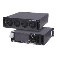
AC power should be wired to L1, L2, and L3 for 3-phase input and L1 & L2 for single phase of the AC Input
Terminal show in the Figure 2-5. Follow the torque requirements as per the figure. Wire ferrules as shown in
Figure 2-6 can be utilized, but are not required.
Recommended input AC wire ferrule:
Manufacturer: Panduit, Manufacturer PN: FSD85-16-L
Manufacturer: Phoenix Contact, Manufacturer PN: 3200577
Figure 2-6 AC terminals and ferrule diagram
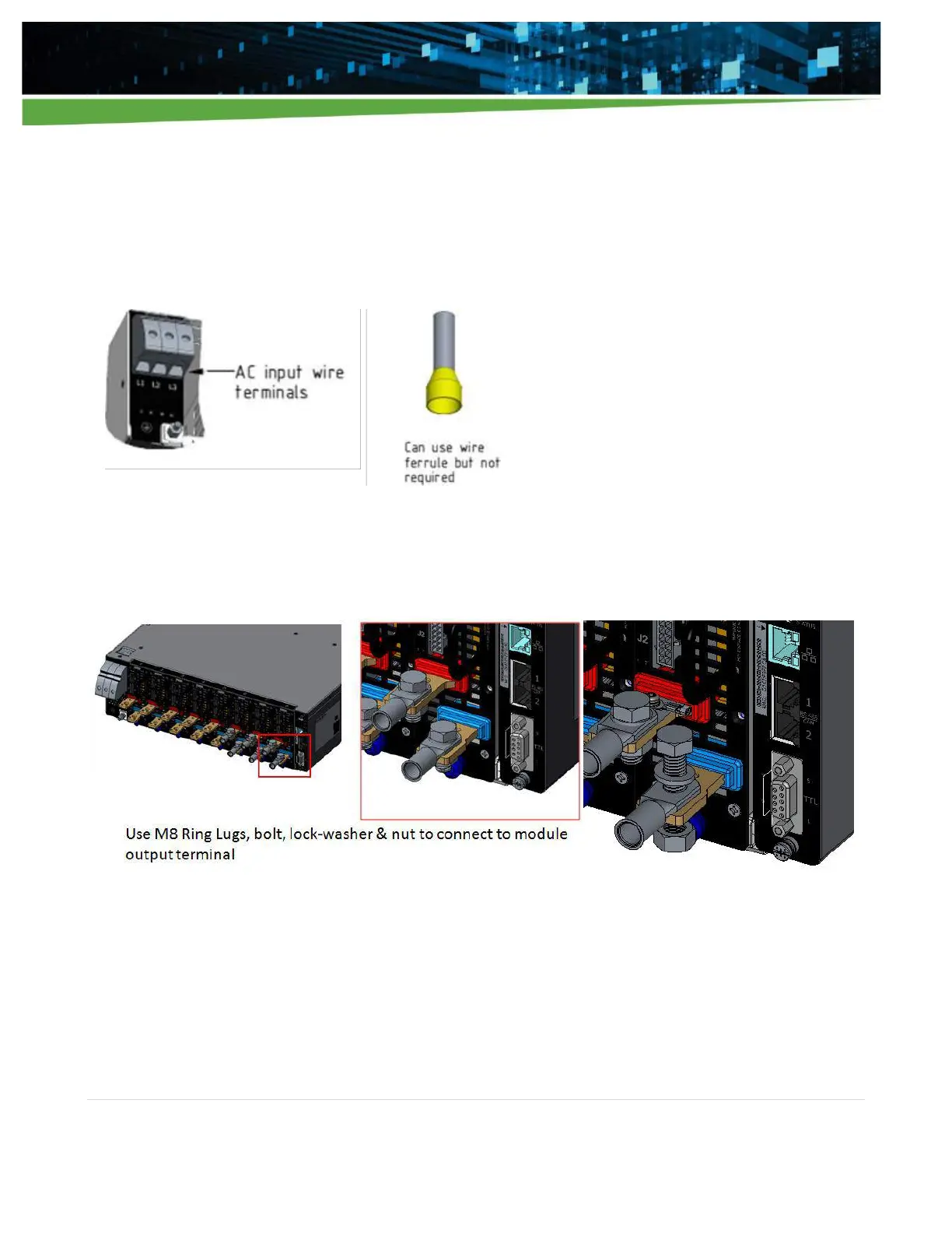
2.5.2 DC Output Wiring
Wire output cables to each iHP module using M8 ring lugs, bolts, and nuts as shown in the Figure 2-7. The
module output busbars are color coded with RED for positive (+) and BLUE for negative (-).
Figure 2-7 DC output wiring diagram
The module types and maximum currents are listed in Table 2-3.