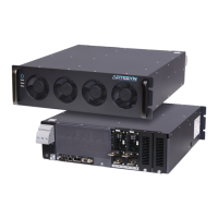
iHP Manual 27 | P a g e
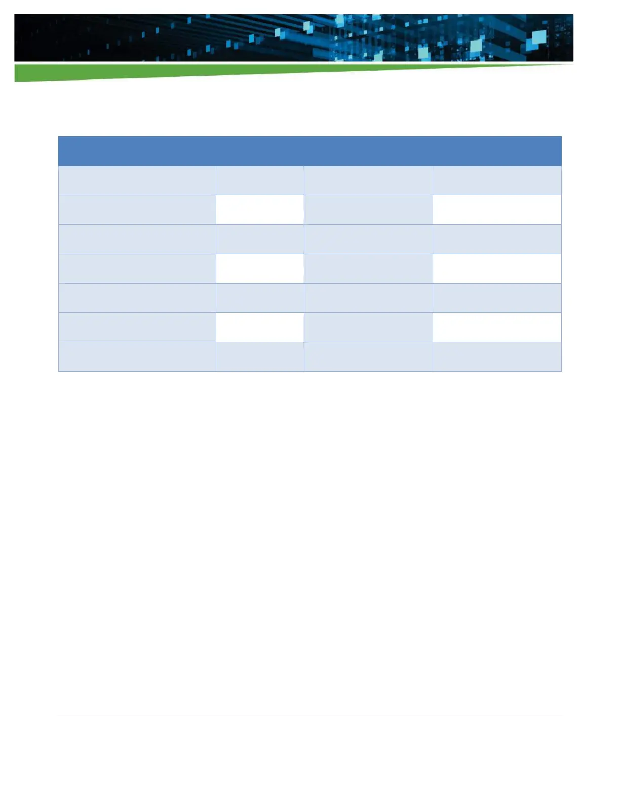
Table 2-3
2.5.3 Remote Sense Wiring
The iHP system uses remote sense to regulate the voltage drops in the system. The module has a negative
(V_SNS-) and a positive (V_SNS+) remote sense to compensate for line drops. Although not needed for
operation, the remote sense wires must be connected to the desire regulated point to be able to meet the
specification regulation limits. Refer to Section 4.2.1 for the location of the remote sense signals in the module
connector J2.
2.5.4 Parallel Module Connection
Same module models can be connected in parallel for higher current applications. A paralleling busbar can be
used to parallel the output modules positive (+) and negative (-) terminals as shown in Figure 2-8. M8 bolt and
nuts should be used. When ordered as a system, the required busbars will be provided to configure the system
as ordered. If reconfiguring a system and a busbar is required for reconfiguration, contact the factory or sales
to obtain the needed busbar.