iHP Manual 43 | P a g e
Operation
4.1 iHP System Power-up
This section explains the initial power up of iHP units. It is assumed in this section that this will be the first
time the iHP rack and iHP module will be powered up after iHP rack and module was manufactured by Artesyn.
4.1.1 Initial Power-up
Discussed in this section are the iHP rack and iHP module default settings when shipped from Artesyn.
Configure the input and output connections to the iHP rack and iHP modules based on user
requirements. Please follow Section 2 for the installation requirement.
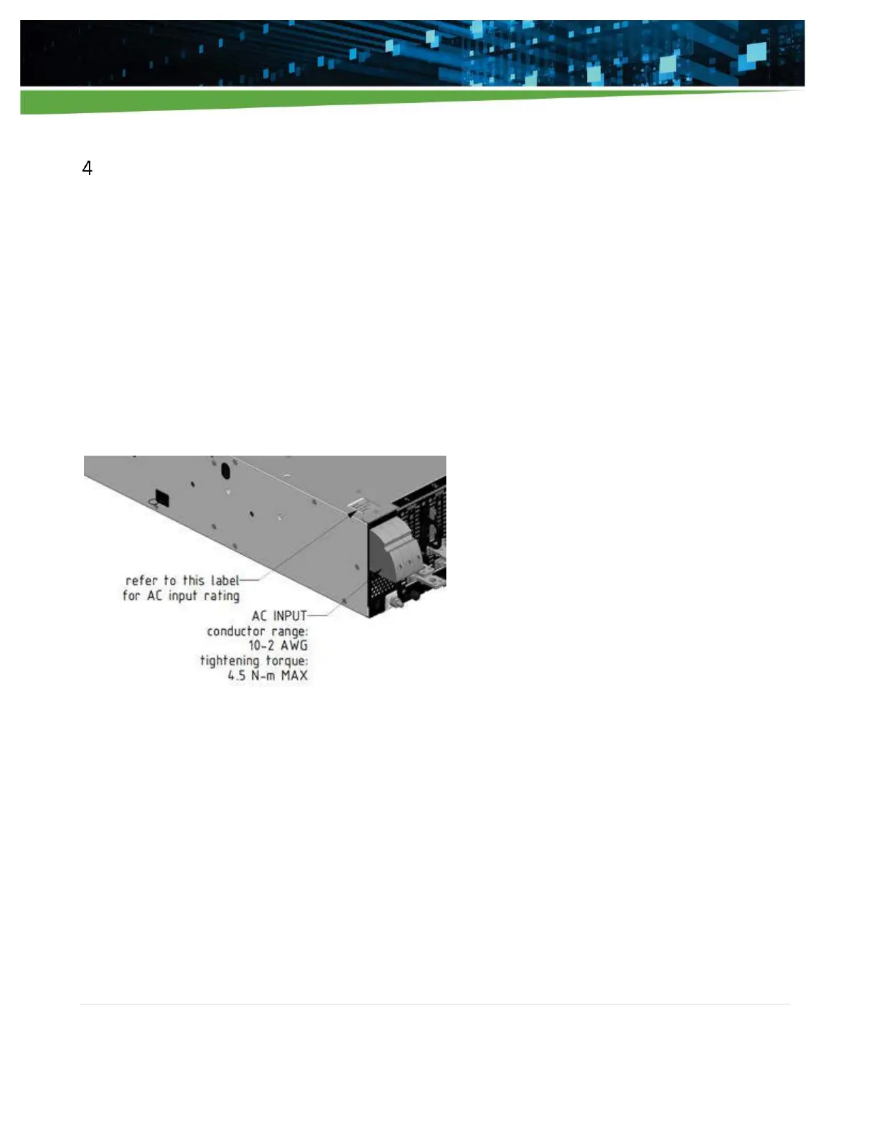
Apply input AC to the iHP rack.
Note: Please follow the allowable input AC parameters located on the AC input rating label of the iHP rack.
Figure 4-1 AC Input connections and AC input rating label location
Upon the application of input AC, the ISOCOMM will undergo boot-up sequence. The fan will momentarily
turn on at full speed and will settle down. The power LED, in the front panel, shown in Figure 4-2, will be
blinking GREEN color during the boot-up sequence. After boot-up sequence, the power LED will be either
steady RED (AC BAD) or steady GREEN (AC OK) depending on the AC power to the iHP rack. For a full list of LED
responses, please refer to Appendix A.