iHP Manual 53 | P a g e
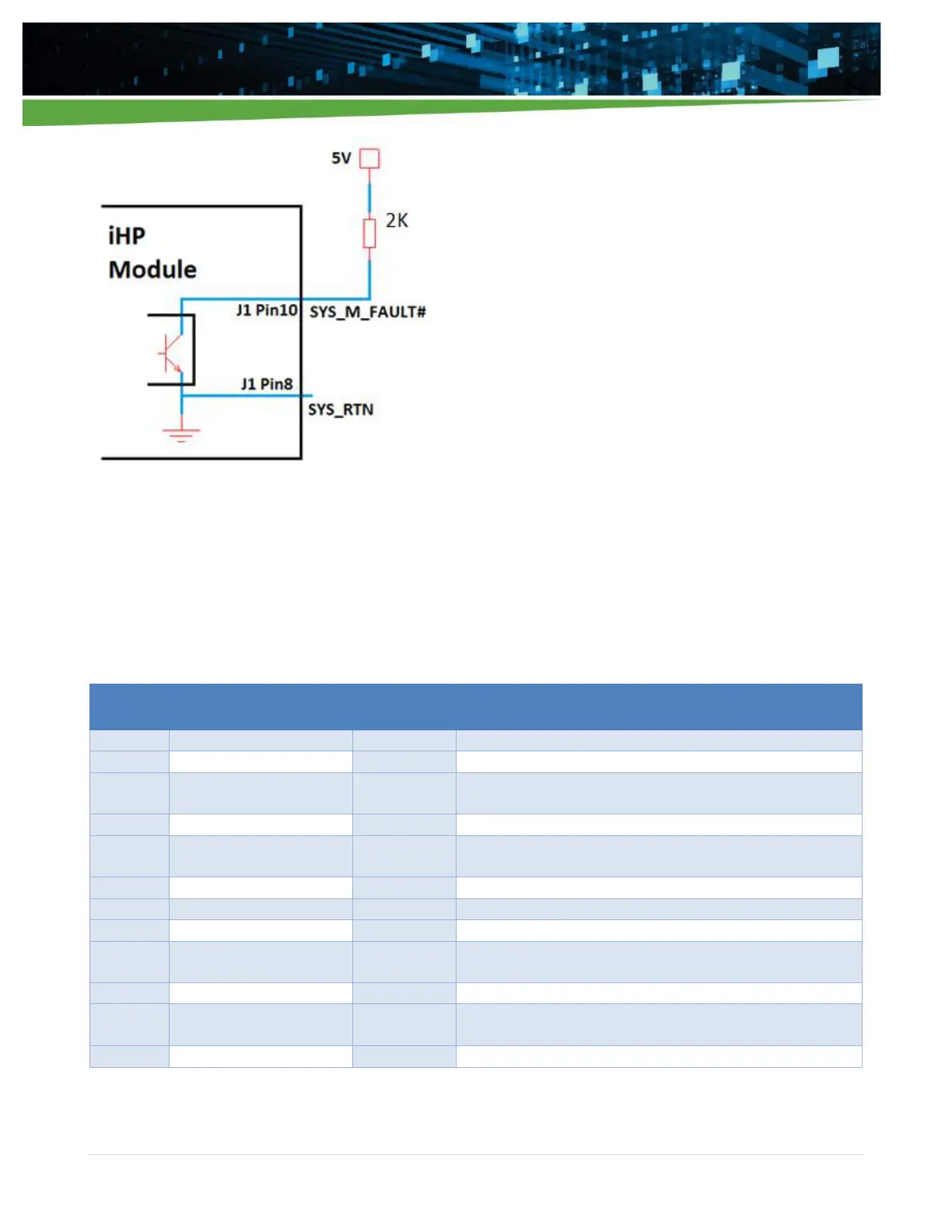
Figure 4-6 Isolated fault signal to signal a module fault condition
4.2.1.2 Module’s J2 Signal
Table 4-8 list the signal information available on connector J2. The module analog connector J2 contains non-
isolated signals. The signal’s circuitry is internally connected and referenced to the module’s output negative
terminal. The module’s J2 signals are isolated from the module’s J1 signals.
Table 4-8
Signal use for module positive remote sense
Ground reference for IMON or VMON signals
Input for external resistor shunt for external current sensing
application.
Ground reference for ISHARE signal
Analog signal to report the output current in scaled value (0-
10V)
Ground reference for IMON or VMON signals
Signal use for module negative remote sense
Input for external resistor shunt for external current sensing
application
Signal for active current sharing
Analog signal to report the output voltage in scaled value (0-
10V)