iHP Manual 51 | P a g e
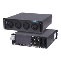
Figure 4-4 Isolated output inhibit circuits to externally inhibit the module.
4.2.1.1.5 Isolated Output Enable
The iHP module provides an input signal to enable output. J1 Pin 9 SYS_M_ENABLE# functions as the
enable signal of the module. This pin is internally connected to an optocoupler’s LED side. An external
1kohms pull up resistor is required. The pull up resistor is connected to a 5V supply. The maximum pull
up resistor voltage is 5V and the maximum sink current is 5mA.
The logic for this pin is configurable via module command SET_IO_ACTIVE_LEVEL_LOGIC (B7h) and can
change the correlation between the output state and the status of the optocoupler’s LED.
The default pin configuration is
Optocoupler LED On = Output is Disabled
Optocoupler LED Off = Output is Enabled
Figure 4-5 shows recommended external circuits to control the enable pin.