EasyManua.ls Logo

Astraada SRV-64 - User Manual

Astraada SRV-64
325 pages
Print Icon
To Next Page IconTo Next Page
Loading...
The owner of Astraada brand is ASTOR Sp. z o.o.
Operation Manual
Astraada SRV-64
AC Servo drives

Table of Contents

Question and Answer IconNeed help?

Do you have a question about the Astraada SRV-64 and is the answer not in the manual?

Overview

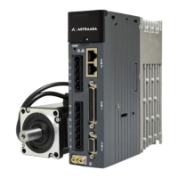
The Astraada SRV-64 AC Servo Drive is a versatile device designed for precise motor control in various industrial applications. It features a modular structure, offering a rich set of functions and excellent performance. The drive supports communication with a host computer via USB, and offers control bus options including Modbus, CANopen, and EtherCAT.

Function Description:

The AS64 series servo drive (100W–2kW) offers a wide range of control modes and functions:

  • Control Modes: Position control, speed control, torque control, switching between position and speed modes, switching between speed and torque modes, switching between position and torque modes, fully-closed loop control, CANopen mode, and EtherCAT mode.
  • Position Control Functions: Clearing residual pulses, inhibiting command pulses, switching electronic gear ratios, and switching vibration control. It provides positioning completion output. Pulse input supports photoelectric coupling (differential input of 4Mpps or open collector input of 200kpps) with pulse + direction, clockwise + counterclockwise (CW + CCW), and orthogonal coding modes. Electronic gear ratios can be set from 1/10000 to 1000. Command smoothing and FIR filters are available. Analog input allows for independent CW or CCW torque limits. Vibration control suppresses 5Hz–200Hz front-end and entire-machine vibration. Pulse output allows arbitrary frequency division settings and supports phase-B reserving. Internal position planning supports 128 segments, controllable via communication.
  • Speed Control Functions: Internal eight-step speeds can be switched based on external control inputs. Speed command ACC/DEC adjustment supports independent ACC/DEC time and S-curve settings. A zero-speed clamp allows hybrid speed or position operation. A first-order delay filter is available for analog input speed commands, with zero-drift suppression accurate to 0.3mV. Speed reaching output is provided. Analog input for speed commands is enabled after relevant settings based on DC±10V analog voltage. Torque limit input allows independent CW or CCW torque limits.
  • Torque Control Functions: Zero-drift clamping input is available, and speed reaching output is provided. Analog input for torque commands allows gain and polarity settings based on analog voltage, accurate to 4.88mV. Analog speed limits are supported. Speed limits can be set via parameters. A first-order delay filter is available for analog input torque commands, with zero-drift suppression accurate to 4.88mV.
  • Homing: Supports LS signal, Phase-Z signal, LS signal + Phase-Z signal, and torque limit signal for homing.
  • Protection: Comprehensive hardware protection against overvoltage, undervoltage, overcurrent, overspeed, overload, brake resistor overload, drive overheating, encoder fault, power phase loss, regenerative brake exception, and fan fault. Software protection includes ROM fault, initialization fault, I/O distribution exception, and excessive position deviation.
  • Fault Recording: Records up to ten faults, including key parameters at the time of fault occurrence.
  • Safety Terminal (STO): Conforms to the latest European safety standards SIL3 (optional).

Important Technical Specifications:

  • Power Supply: 1PH/3PH, AC 220V (±15%), 47Hz–63Hz.
  • Control Signal Inputs: 8 for standard, pulse, and CANopen bus types; 7 for EtherCAT bus type (configurable).
  • Control Signal Outputs: 6 single-way for standard, pulse, and CANopen bus types; 4 differential for EtherCAT bus type.
  • Analog Inputs: 2 standard (two 16-bit) and 2 other (two 12-bit).
  • Analog Outputs: 2.
  • Pulse Signal: 1 group of open collector or differential input; 1 group of differential outputs (A+/A-; B+/B-; Z+/Z-).
  • Encoder 2 Input: Incremental encoder (or grating ruler) interface or serial communication interface.
  • Communication: USB (1:1 with host software, preconfigured), RS485 (1:n, preconfigured), CANopen (1:n, optional), EtherCAT (1:n, optional).
  • Environmental Conditions:
    • Working temperature: 0–45°C
    • Storage temperature: -20–80°C (no freezing)
    • Working/storage humidity: ≤90%RH (no condensation)
    • IP rating: IP20
    • Altitude: Below 1000m
    • Vibration: ≤5.88m/s², 10–60Hz (not allowing work at resonance point).

Usage Features:

  • Installation: Designed for vertical installation with specific clearance requirements for proper ventilation. A fan may be needed if the control cabinet temperature exceeds 45°C.
  • Wiring: Detailed instructions for system wiring, main circuit terminals, motor power cables, control I/O (CN1), encoder (CN2), RS485/CAN (CN3), USB (CN4), second-encoder (CN5), and STO (CN11). Emphasizes using shielded cables for analog control and frequency input signals, and proper grounding techniques.
  • Operation: First power-on procedures include verifying correct wiring, ensuring no short circuits, proper grounding, and external servo enabling terminal (SON) is OFF. Setting the motor code (P0.00) is crucial for proper motor operation.
  • Jogging: Trial run by jogging is available to check system condition and commission. Jogging speed, acceleration, and deceleration times are configurable.
  • Parameter Adjustment: Parameters can be adjusted via the LED panel, PC software, or communication. Both automatic and manual tuning methods are supported. Automatic tuning involves setting load inertia ratio and mechanical rigidity. Manual tuning allows fine-tuning speed loop gain, integral time constant, torque command filtering, and APS gain to optimize performance and suppress vibrations.
  • Mechanical Resonance Suppression: Equipped with four notch filters to suppress mechanical resonance by adjusting frequency, Q factor, and depth.
  • Gain Switching: Allows switching between different gain sets (e.g., for position, speed, or torque control) based on internal data or external signals, improving responsiveness and stability.
  • Software: Astraada DRIVE Studio provides a comprehensive interface for monitoring, commissioning, parameter setting, fault diagnosis, and advanced functions like frequency feature testing and electronic cams.

Maintenance Features:

  • Fault Handling: Provides a detailed list of fault codes (ErXX-X format) with possible causes and workarounds. Faults can be cleared online (if conditions allow) by shorting the digital input fault clearing terminal or by repowering the drive.
  • Encoder Battery Replacement: For multiturn absolute encoders, the battery should be replaced only when the drive power is on to prevent loss of absolute position data. The standard battery has a replacement cycle of 1.5–2 years.
  • EEPROM Management: Parameters can be saved to EEPROM individually or in batches. The drive can also restore factory settings.
  • Fault Records: The drive records up to ten fault events, including power-on time, running time, motor speed, speed command, accumulated feedback pulses, accumulated command pulses, residual pulses, output torque, main circuit DC voltage, output voltage, and output current at the time of the fault. These records can be read for diagnosis.

Astraada SRV-64 Specifications

General IconGeneral
BrandAstraada
ModelSRV-64
CategoryServo Drives
LanguageEnglish