AS64 series AC servo drive Control modes
-54-
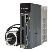
4.5.3 Analog input circuit wiring
0
0
0
20 AD1
6 GND
7 AD2
A
D
C
FG
Connect the shielded
cable according to
device requirements
Twisted
pair
6 GND
0
0
0
Drive side
Control
module side
In the two analog input circuits: AD1 is accurate to 16 bits (optional, applicable only to standard models)
and AD2 is accurate to 12 bits (preconfigured for standard models); the input impedance is 10kΩ, and
the input voltage ranges from -10V to +10V. If the voltage is ±11V less or greater, the circuit may be
damaged.
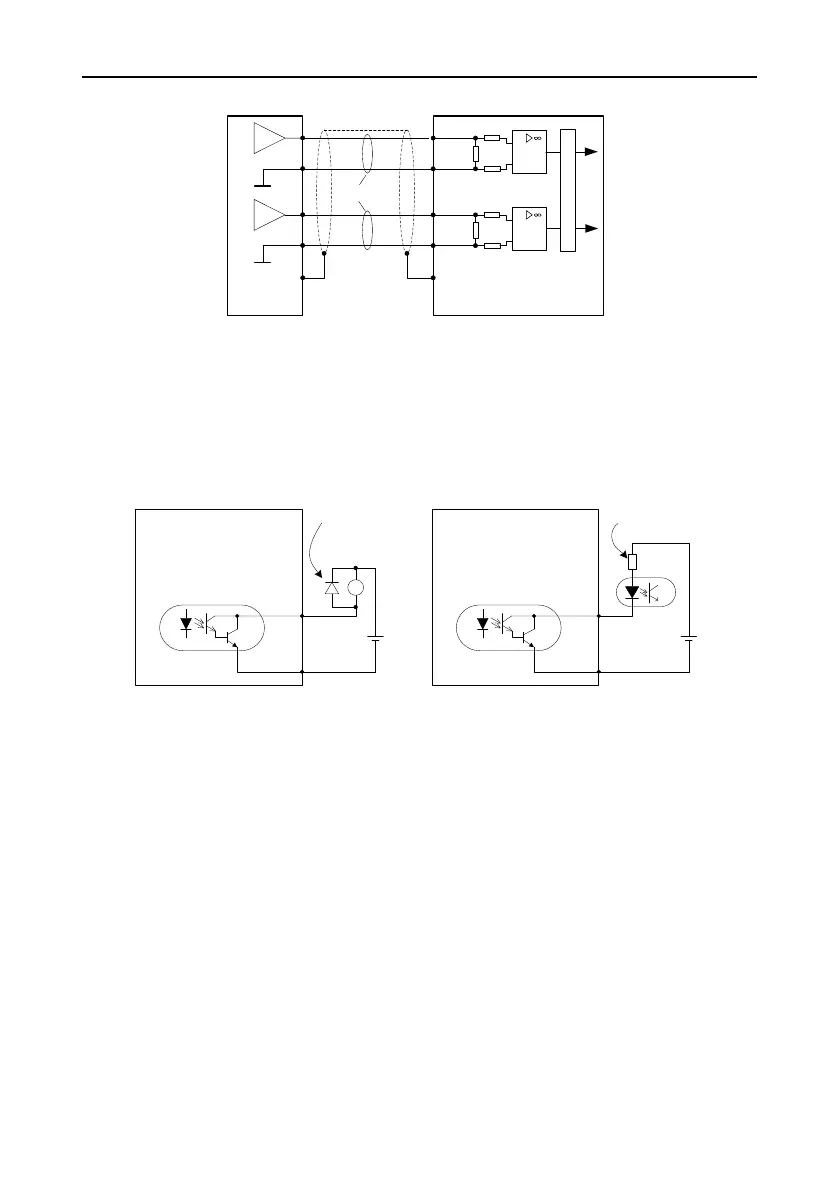
4.5.4 Digital output circuit wiring
Wiring method in which user-provided power is used
Connect a free-wheeling
diode if an inductive load is
connected.
Max load capacity of each
output terminal: 30V, 50mA
DC
12~24V
+
-
Drive side
DO1- 5
Max. load capacity of each
output terminal: 30V, 50mA
+
-
RY
DC
12~24V
Connecting to a relay coil
Connecting to an optical coupler
DO1- 5
Connect to a current limit
resistor if an optical coupler
is connected.
Drive side
DO1+ 14
DO1+ 14
⚫ There are six digital output circuits in total, which use the open-collector output structure as shown
in the figure. They can be used to drive the relay coil or optical coupler load. The loading capacity
is shown in the figure.
⚫ If an inductive load such as the relay coil is connected, a free-wheeling diode must be connected,
as shown in the figure. If an optical coupler is connected, a current limit resistor must be connected.
Otherwise, the drive may be damaged.