AS64 series AC servo drive Control modes
-57-
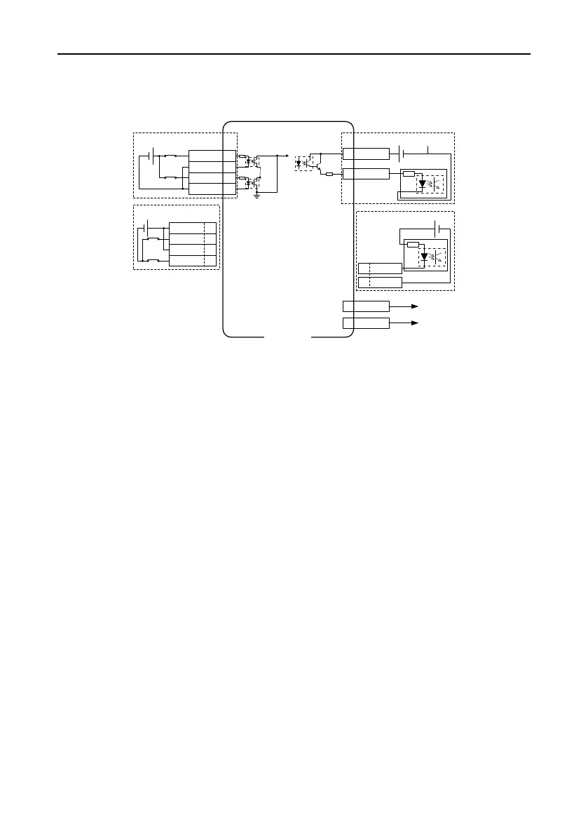
4.7 Wiring description for CN11
Wiring for the safety terminal circuit
The STO function achieves motor current cut-off through hardware.
To be specific, the independent circuits for input signals in two channels are used to prevent the drive
signal from the power module that controls motor current, and thus the power module cuts off the
motor current.
If the input optical couplers corresponding to HWBB1 and HWBB2 are both connected, the system
runs properly, and the safety output signal EDM is invalid.
If either the input optical coupler corresponding to HWBB1 or that corresponding to HWBB2 is
disconnected, the drive does not power the motor, the LED panel displays "STO_IN", and the safety
output signal EDM is valid.