AS64 series AC servo drive Control modes
-55-
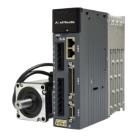
4.5.5 Frequency-division output circuit wiring of encoder feedback signals
Differential method:
Drive side
OA+ 44
OA- 43
OB+ 41
OB- 42
OZ+ 28
OZ- 27
GND 6
Twisted
pair
Terminal
resistor
AM26LS32
or equivalent chip
GND
Shielded
cable
Connect the shielded
cable according to
device requirements
⚫ Phases A, B, and Z of the encoder provide differential output signals. You are recommended to
use AM26C32 or equivalent chip and connect an end-matching resistor of about 220Ω.
⚫ No isolation is made for any output circuit.
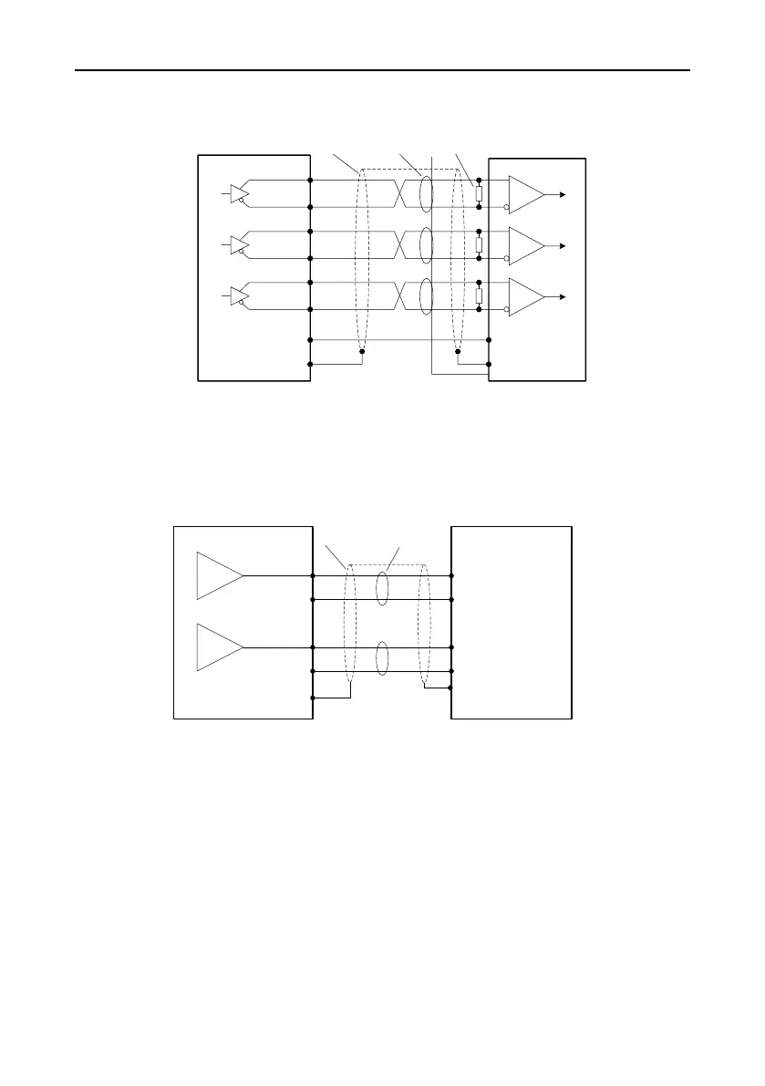
4.5.6 Analog output circuit wiring
Measuring instrument or
external circuit
Shielded
cable
Connect the shielded
cable according to device
requirements
Servo drive
Twisted
pair
GND
GND
AI1
AI2
AO1 21
AO2 25
GND 6
GND 6
FG
There are two analog output circuits in all. The output voltage range is -10V–10V. The maximum output
current is 3 mA.
4.5.7 Electromagnetic brake wiring
If the servo motor is used to drive the vertical shaft, the electromagnetic brake can be used to prevent
against the falling of heavy objects or keep the falling speed when the servo drive is powered off. See
the following wiring diagram for the electromagnetic brake.
 Loading...