AS64 series AC servo drive Operating and running
-66-
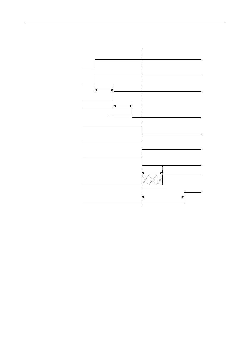
5.1.9 Timing sequence
5.1.9.1 Timing sequence for power-on and servo turning on
Main power
Control power
PWM output
Electromagnetic
brake release signal
output (BRK)
Servo enabling
(SON)
Microprocessor
state
Note 1: The delay time from microprocessor initialization completion to servo readiness output can be set
by P4.54.
Note 2: The condition for the RDY output signal electric level to become low is: The servo has no fault and
main circuit DC voltage has been established, with voltage higher than 250V/430V (for 220V/400V series). If
the main circuit DC voltage is less than 170V/310V (for 220V/400V series), the Er13-1 alarm is reported.
The time interval from servo readiness to servo enabling can be user controlled.
Note 3: The servo enabling signal can be valid only when the RDY output signal is valid.
Note 4: The actual electric levels corresponding to valid I/O states can be set by P3.00–P3.15.
Position/speed/torque
command input
About 1.2s
Note 3
200ms
Control circuit powered on
Main circuit
powered on
Program started running
Servo without output
Motor brake releasedMotor brake closed
Servo with output
Command input invalid
Command
input valid
Fan signal
Fan running
Fan not run
Powering-on process
Servo turning-on
process
100ms
Program initialized
Servo readiness
(RDY)
Note 2
Note 1
Invalid
Invalid
Valid
Valid
Note 4
Brake being
released