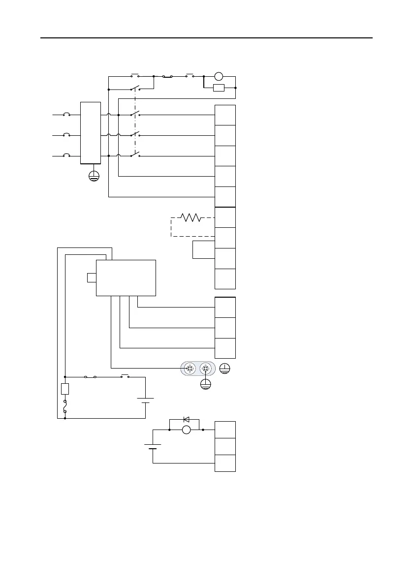
· Input voltage of power:
AC 220V(±15%)
· Connect the servo motor cables
to the drive output terminals U, V,
and W according to the correct
phase sequence. Incorrect phase
sequence may cause a drive
fault.
· Ground the servo drive properly.
Otherwise, electrical shocks may
be caused.
· Prepare the 24VDC power for
electromagnetic braking by
yourself and isolate it from the
DC12~24V power for signal
control.
· Pay attention to free-wheeling
diode connection. Reversed
polarity may cause drive damage.
· Employ this emergency stop
circuit.
· Add a surge absorber to each end
of the electromagnetic contactor
coil.
Yellow/
Green
Surge
absorber
Fuse
Breaker MC
MC
ALM
CN1
Emergency
stop button
RY
EMI
filter
DC 12~24V
(±10%)
DC 24V
(±10%)
OFF ALMON
+
-
+
-
Motor
L1
L2
L3
L1C
L2C
B3
+
B2
U
V
W
-
DO-
DO+
· Do not remove the short-
connection cable between B2 and
B3 (for a drive of 750W or greater)
unless an external regenerative
brake resistor is used.
· If you use an external regenerative
brake resistor, remove the
connection cable between B2 and
B3 and connect the resistor as
shown in the dashed box.