AS64 series AC servo drive Wiring instructions
-29-
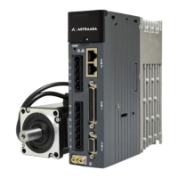
Power ground for CAN chip
The same interface is
provided for RS485 and
CAN communication.
Each signal occupies two
pins, which facilitates
multidevice networking.
Power ground for RS485 chip
Note: If the drive uses the EtherCAT bus, this port is the standard network cable port, which indicates
that pin 1, pin 2, pin 3, and pin 6 correspond to Tx+, Tx-, Rx+, and Rx- respectively.
3.7 Wiring for USB terminal CN4
The standard cable for converting mini
USB to USB-A can be used.
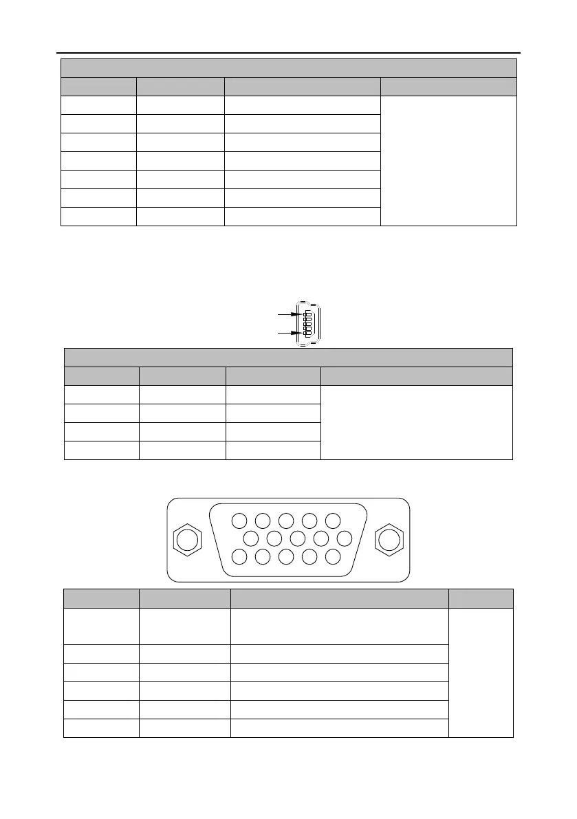
3.8 Wiring for second-encoder terminal CN5
5 4 3 2 1
10 9 8 7 6
15 14 13 12 11
Parallel encoder signal V+/Encoder serial
data+
Connected
to the
grating
ruler or
second
encoder.
Parallel encoder signal W+
Parallel (or second) encoder signal A+
Parallel (or second) encoder signal A-
Parallel encoder signal U+