This parameter specifies the gain of analog input 1, the gain unit is associated with P3.26.
Note:
⚫ Analog input 1 indicates the signal input from the terminals (that is, AD1 and GND,
corresponding to pin 1 and pin 5) of analog input 1 of the CN1 plug.
⚫ The voltage only in the -10V–+10V range can be applied to the connection between AD1 and
GND. Otherwise, the drive may be damaged.
Application example:
1. The function of analog input 1 is speed command.
2. The voltage of analog input 1 corresponds to the conversion gain of the motor command
speed.
3. P0.40 is set to 1.
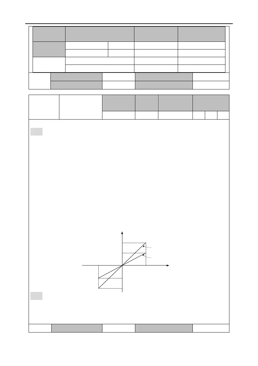
4. The relationship between the voltage of analog input 1 and speed command is as follows:
Every 1V voltage corresponds to the 100 r/min speed by default.
Actual speed command = Analog input voltage x P0.42
Note:
⚫ This parameter is valid only when P0.40 is 1.
⚫ Set this parameter according to the motor working condition. If this parameter is set to a large
value, the motor speed may fluctuate sharply.