EasyManuals Logo

Avnet Qseven MSC Q7-BT User Manual

Avnet Qseven MSC Q7-BT
113 pages
To Next Page IconTo Next Page
To Previous Page IconTo Previous Page
Page #17 background imageLoading...
Page #17 background image
MSC Q7-BT MSC_Q7-BT_User_Manual.pdf 17 / 113
1.3 Power Supply
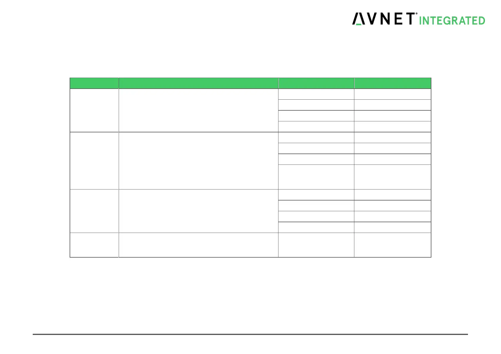
Table 1-1 Module Power Inputs
Power Rail
Description
VCC
Primary power input
Nominal
+5V
Voltage Range
+4.75V ... +5.25V
Max. Input Ripple
±50mV
Max. Voltage Rise rate
< 250V/s
VCC_5V_SB
Standby power input
All available VCC_5V_SB pins on the connector(s) shall
be used.
Used for microcontroller, standby and suspend functions
on the module.
If no standby power is available on carrier board connect
to VCC (primary power input).
Nominal
+5V
Voltage Range
+4.75V ... +5.25V
Max. Input Ripple
±50mV
Rate of Voltage Rising
< 250V/s
VCC_RTC
Real-time clock circuit-power input in system power state
G3 (mechanical off)
Optional; can be left open.
Nominal
+3V
Voltage Range
+2.0V ... +3.3V
Max. Input Ripple
±20mV
Current (G3)
typ. 6 uA; max. 100uA
GND
Power and signal return path. All available GND
connector pins shall be used and tied to Carrier Board
GND plane.

Table of Contents

Questions and Answers:

Question and Answer IconNeed help?

Do you have a question about the Avnet Qseven MSC Q7-BT and is the answer not in the manual?

Avnet Qseven MSC Q7-BT Specifications

General IconGeneral
BrandAvnet
ModelQseven MSC Q7-BT
CategoryControl Unit
LanguageEnglish

Related product manuals