AW00089317000 Image Acquisition Control
Basler ace GigE 109
7.5 acA750 - Acquisition Control
Differences
7.5.1 Overview
In almost all respects, acquisition triggering on acA750 model cameras adheres to the acquisition
control description provided throughout in this chapter. But because the acA750 models have an
interlaced sensor (rather than the standard progressive scan sensor used on the other camera
models), there are some significant differences.
With the architecture of the acA750 sensor, there is only one vertical shift register for each two
physical pixels in the sensor. This leads to what is commonly known as a "field" readout scheme for
the sensor. There are two fields that can be read out of the sensor "Field 0" and "Field 1". The main
difference between Field 0 and Field 1 is that they combine the pixels in the sensor rows in different
ways.
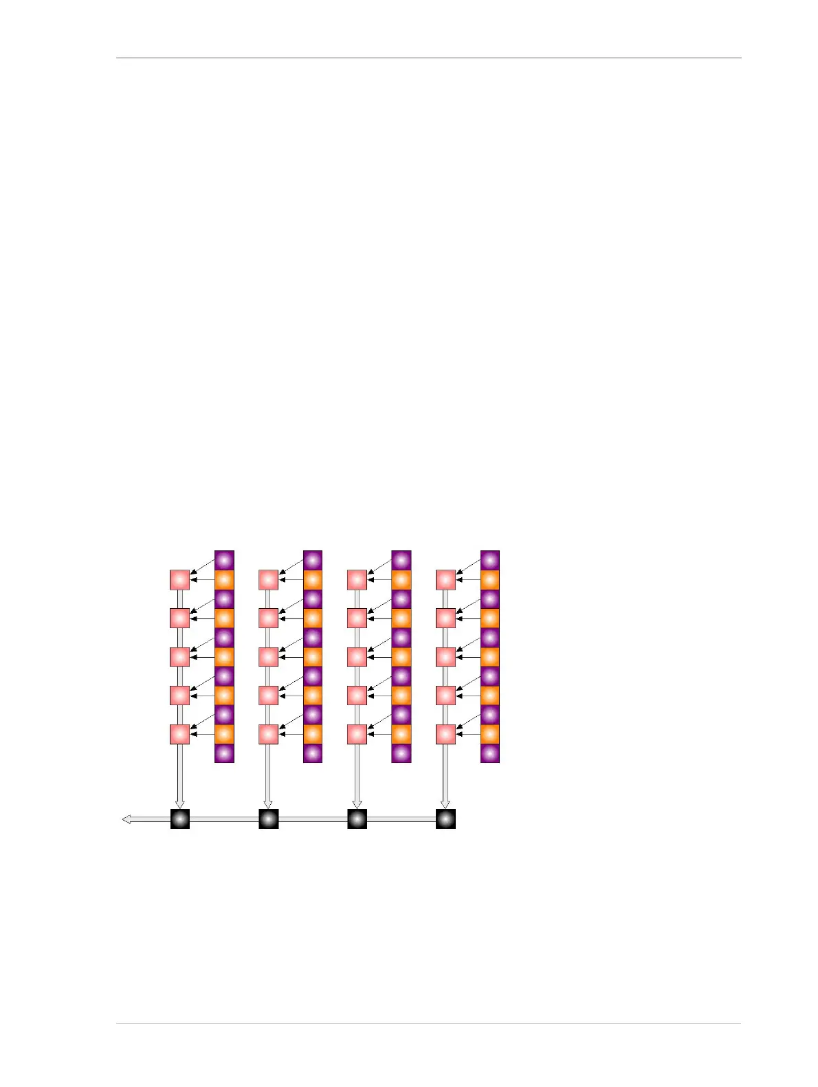
As shown in Figure 55, with Field 0 readout the pixel values from row 0 are binned with the pixel
values from row 1, the pixel values from row 2 are binned with the pixel values from row 3, the pixel
values from row 4 are binned with the pixel values from row 5, and so on.
Row 0
Row 1
Row 2
Row 3
Row 4
Row 5
Row 6
Row 7
Row 8
Row 9
Row 10
Pixels
Vertical
Shift
Registers
Horizontal Shift Registers
Fig. 55: Field 0 Readout
Note: The colors used in this drawing are designed to
illustrate how the camera’s output modes work. They
do not represent the actual colors used in the color
filter on acA750-30gc cameras.

 Loading...


