Physical Interface AW00089317000
64 Basler ace GigE
5.7.2 Characteristics
The camera is equipped with one physical input line designated as Input Line 1. The input line is
accessed via the 6-pin receptacle on the back of the camera.
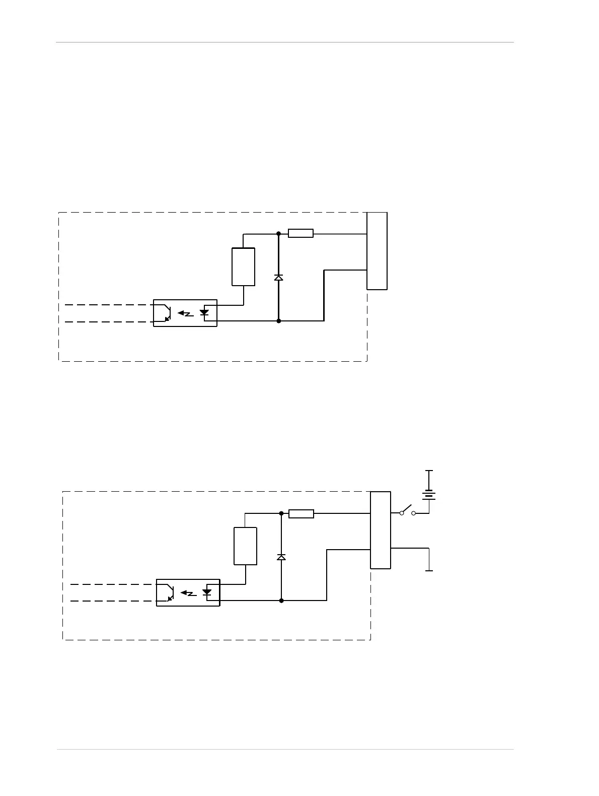
As shown in Figure 39, the input line is opto-isolated. See the previous section for input voltages
and their significances. The current draw for each input line is between 5 mA and 15 mA.
Figure 40 shows an example of a typical circuit you can use to input a signal into the camera.
1
2
3
4
5
6
6-Pin
Receptacle
I/O_In_1
I/O_Gnd
In_1_Ctrl
Camera
10
Fig. 39: Input Line Schematic (Simplified)
Current
Limiter
Your
Gnd
Your
Gnd
Input
Voltage
+30 VDC
Absolute
Max.
6-Pin
Receptacle
1
2
3
4
5
6
I/O_In_1
I/O_Gnd
In_1_Ctrl
Camera
10
Fig. 40: Typical Input Circuit (Simplified)
Current
Limiter

 Loading...


