I/O Control AW00089317000
76 Basler ace GigE
6.2.3 Setting the Output Line for Invert
You can set the output line to not invert or to invert.
When the output line is set to not invert:
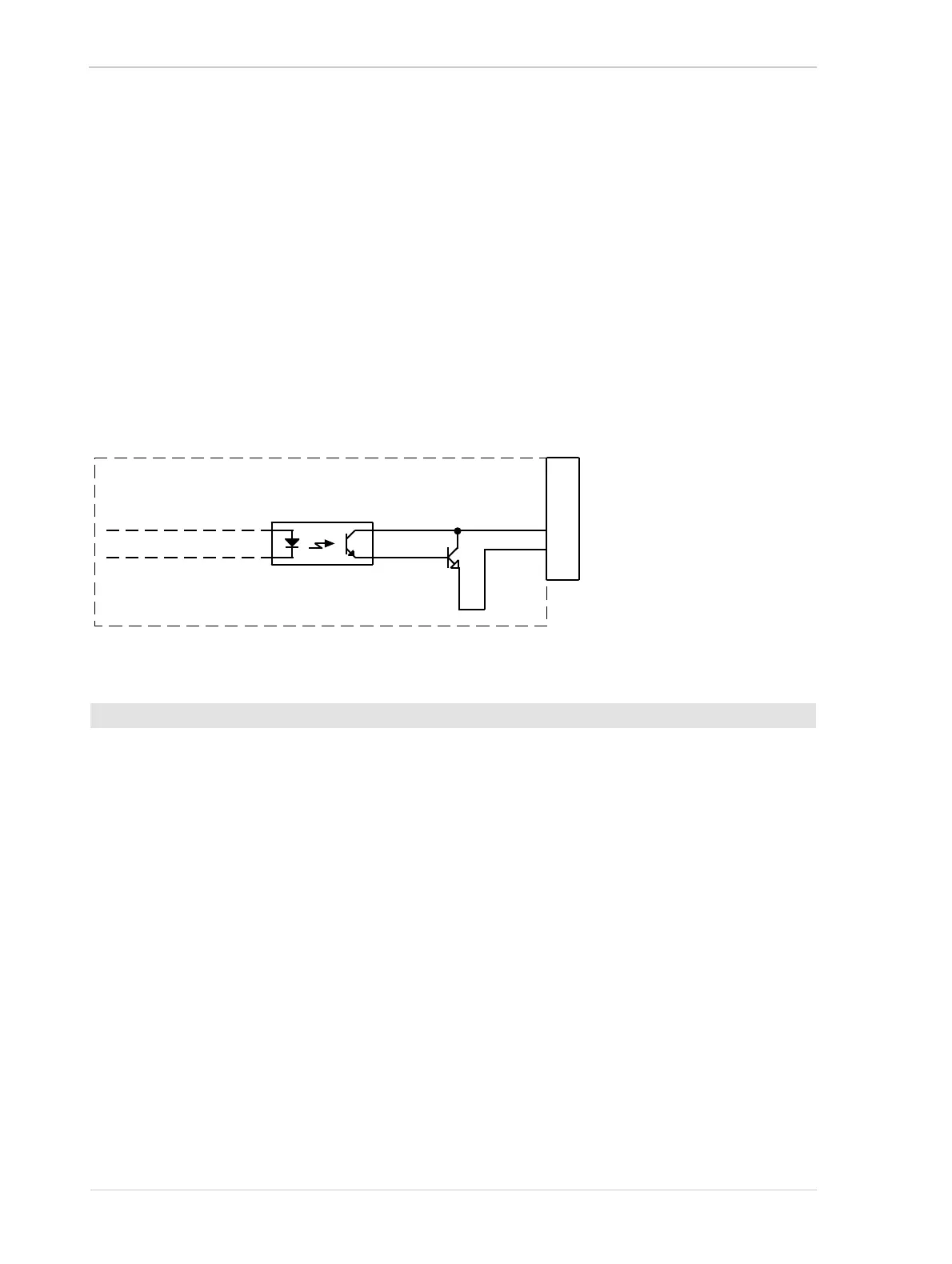
A logical zero on Out_1_Ctrl results in a non-conducting Q1 transistor in the output circuit (see
Figure 47).
A logical one on Out_1_Ctrl results in a conducting Q1 transistor in the output circuit.
When the output line is set to invert:
A logical zero on Out_1_Ctrl results in a conducting Q1 transistor in the output circuit.
A logical one on Out_1_Ctrl results in a non-conducting Q1 transistor in the output circuit.
1. Use the Line Selector to select output line 1.
2. Set the value of the Line Inverter parameter to true to enable inversion on the selected line or
to false to disable inversion.
You can set the Line Selector and the Line Inverter parameter values from within your application
software by using the Basler pylon API. The following code snippet illustrates using the API to set
the selector and the parameter value:
// Enable the inverter on output line 1
Camera.LineSelector.SetValue( LineSelector_Out1 );
Camera.LineInverter.SetValue( true );
You can also use the Basler pylon Viewer application to easily set the parameters.
For more information about the pylon API and the pylon Viewer, see Section 3.1.1 on page 45.
To set the invert function on the output line:
Fig. 47: Output Line Schematic (Simplified)
1
2
3
4
5
6
6-Pin
Receptacle
I/O_Out_1
I/O_Gnd
Q1
Camera

 Loading...


