Physical Interface AW00089317000
70 Basler ace GigE
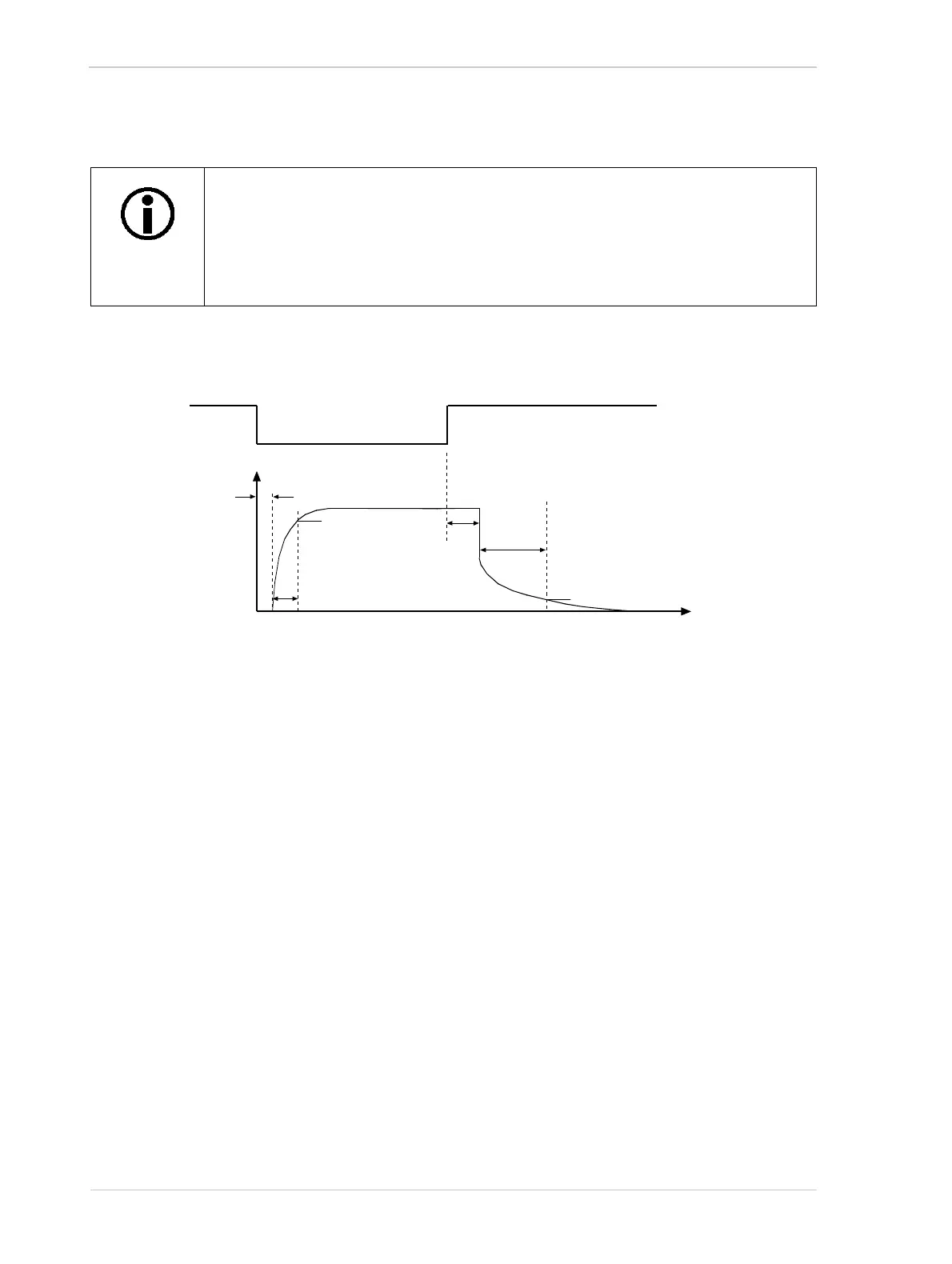
5.8.3 Output Line Response Time
Response times for the output line on the camera are as shown in Figure 45.
Time Delay Rise (TDR) = 40 µs
Rise Time (RT) = 20 µs to 70 µs
Time Delay Fall (TDF) = 0.6 µs
Fall Time (FT) = 0.7 µs to 1.4 µs
5.8.4 Selecting a Source Signal for the Output Line
To make the physical output line useful, you must select a source signal for the line. The camera
has several standard output signals available and any one of them can be selected to act as the
source signal for the output line.
For more information about selecting a source signal for the output line, see Section 6.2 on
page 74.
The information in this section assumes that the output circuit on your camera is
designed as in the typical voltage output circuit shown in Section 5.8.2.
The response time for the output line on your camera will typically fall into the
ranges specified below. The exact response time for your specific application will
depend on the external resistor and the applied voltage you use.
Time
TDR
RT
TDF
FT
90%
90%
Not to Scale
Level on
Out_1_Ctrl
Voltage Present
on the Camera’s
Output Line
Fig. 45: Output Line Response Times

 Loading...


