AW00089317000 Physical Interface
Basler ace GigE 65
For more information about
input line pin assignments and pin numbering, see Section 5.2 on page 56.
how to use an externally generated frame start trigger (ExFSTrig) signal to control acquisition
start, see Section 7.4.3 on page 103.
configuring the input line, see Section 6.1 on page 71.
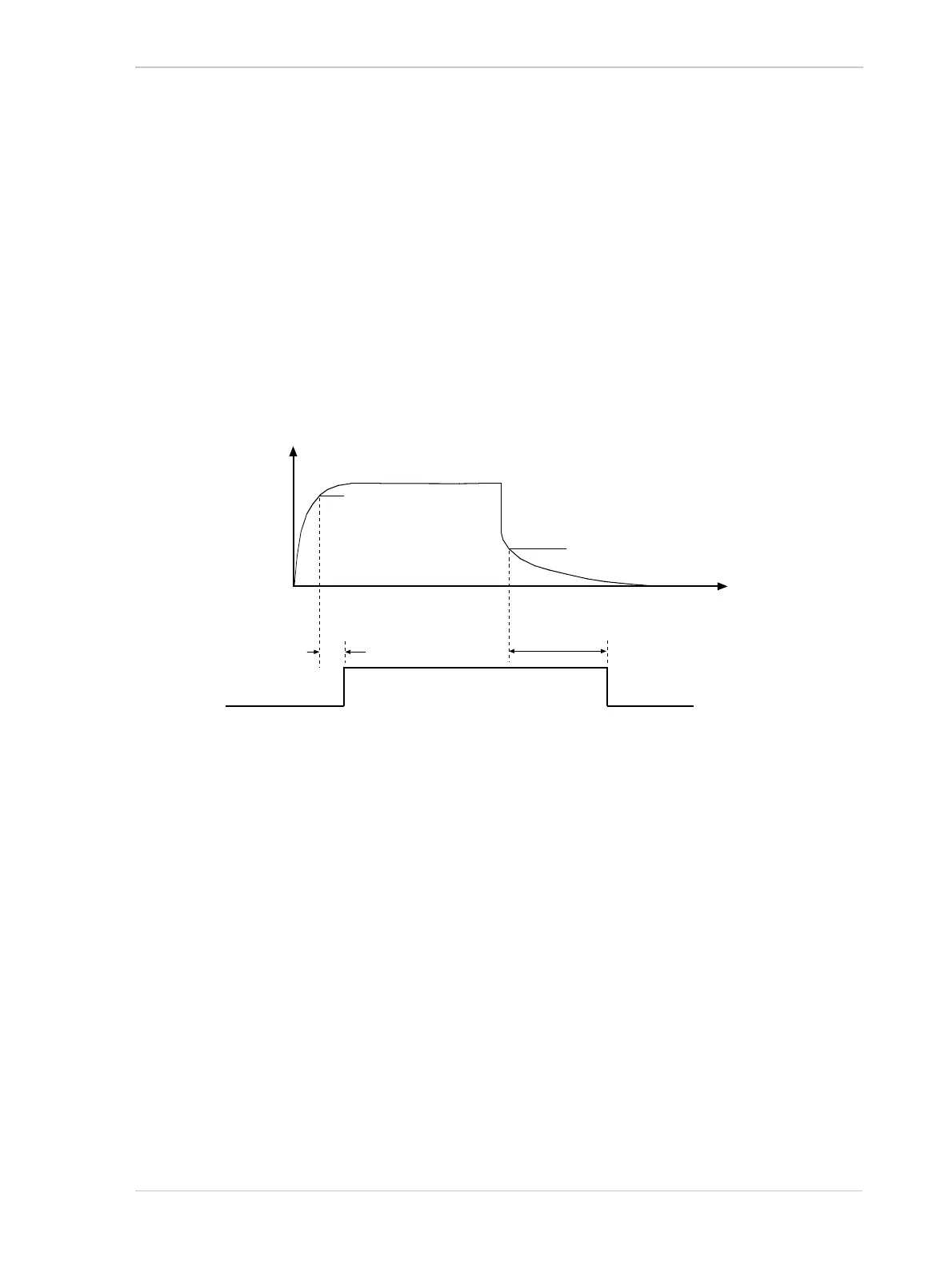
5.7.3 Input Line Response Time
The response times for the input line on the camera are as shown in Figure 41.
Time Delay Rise (TDR) = 1.3 µs to 1.6 µs
Time Delay Fall (TDF) = 40 µs to 60 µs
Level of
Camera’s
Internal Input
Circuit
Voltage Applied
to the Camera’s
Input Line
Time
TDR
TDF
2.2 V
(10.4 V with PLC cable)
1.4 V
(8.4 V with PLC cable)
Not to Scale
Fig. 41: Input Line Response Times

 Loading...


