Image Acquisition Control AW00089317000
110 Basler ace GigE
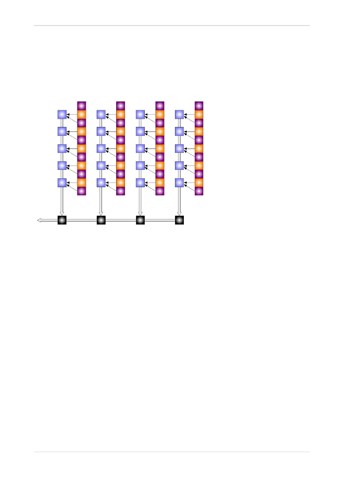
As shown in Figure 56, with Field 1 readout the pixel values from row 1 are binned with the pixel
values from row 2, the pixel values from row 3 are binned with the pixel values from row 4, the pixel
values from row 5 are binned with the pixel values from row 6, and so on
Pixels
Vertical
Shift
Registers
Horizontal Shift Registers
Fig. 56: Field 1 Readout
Row 0
Row 1
Row 2
Row 3
Row 4
Row 5
Row 6
Row 7
Row 8
Row 9
Row 10
Note: The colors used in this drawing are designed to
illustrate how the camera’s output modes work. They
do not represent the actual colors used in the color
filter on acA750-30gc cameras.

 Loading...


