7-14
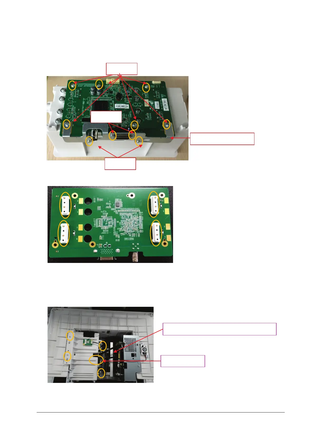
4. Place the face of the removed module rack assembly board up. First unscrew the two M2.5X6 screws on the SMR
interface, the two PT3X8 screws, and the six M3X6 screws in turn, and then take down the internal module rack
COM board.
5. Turn over the removed internal module rack COM board, and take down the four POGO PIN silicon cases.
N15/M15/N17/M17
1. First remove the connection line of internal module rack COM board; unscrew the four M3X6 screws according to
the positions shown below, and loosen one captive screw; force upward vertically to remove the module rack
assembly as indicated in the figure.
2. Place the face of the removed module rack assembly board up. First unscrew the two M2.5X6 screws on the SMR
interface, the two PT3X8 screws, and the seven M3X6 screws in turn, and then take down the internal module rack
COM board.
One captive
Connection line of internal module rack COM board
SMR interface sheet metal
PT3X8
M2.5X6
M3X6