7-18
(N15)
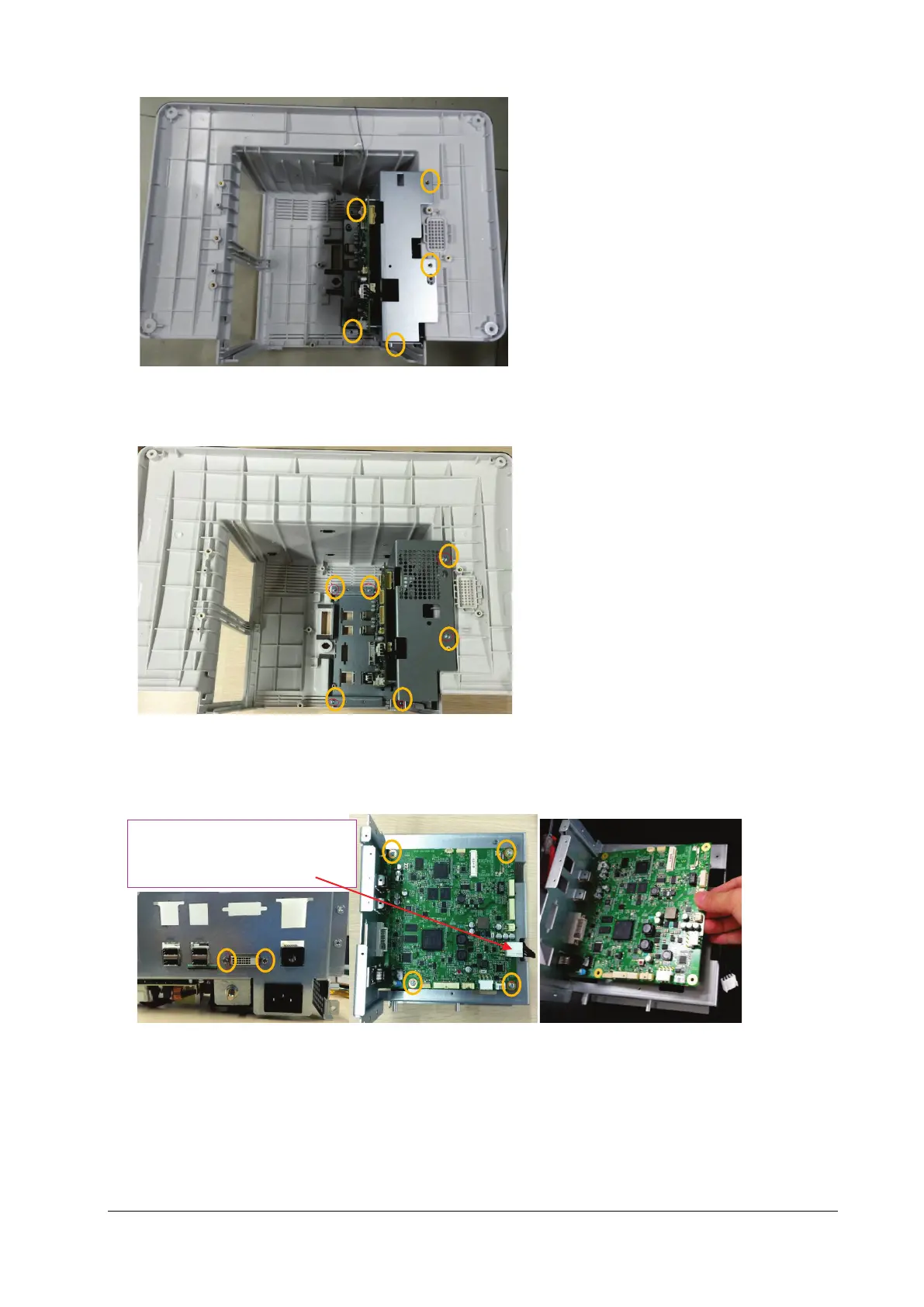
As shown below, for the N17/M17 series machine, loosen and remove the six M3X6 screws, and vertically take out
the main support assembly.
(N17)
3. As shown in the figure below, place the face of the removed main board of main support up, pull out the
connection line from the main control board to the ACDC and insert it in the main board end, loosen and remove
the two DVI stud screws and four M3X6 screws, and then take out the main control board.
4. Turn over the main support with the main control board removed, and place its face up; remove the connection
line from the main control board to the ACDC, and insert it into the ACDC power supply end; remove the power
cord from the AC input to the ACDC, and insert it into the ACDC power supply end; loosen and remove four M3X6
screws, and take down the power board.
Connection line from the main
control board to the ACDC