7-25
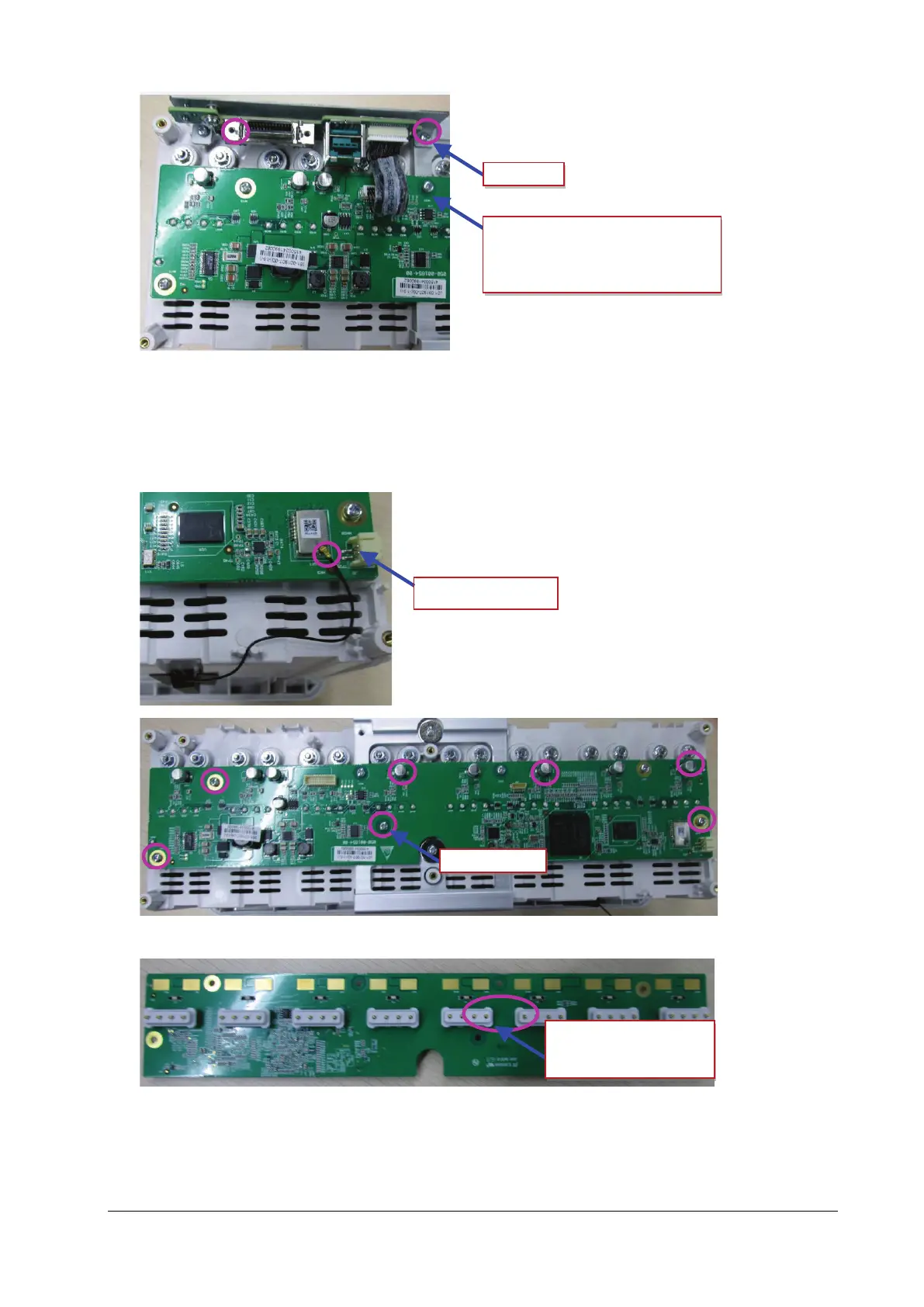
4. Removing the internal module rack COM board.
Pull out the connection line between the module rack antenna and the internal module rack COM board, loosen
and remove the seven M3X8 cross recessed pan head screws on the internal module rack COM board, and take
down the eight POGO PIN silicon cases of module rack.
Connection line from the interface
board of external module rack to the 8
-
POGO PIN silicon cases of
module rack