M (E3.1) 1/2023 page 20/136
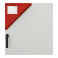
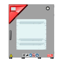
2.3 Triangular instrument panel
5,7" controller display with touchscreen
USB interface
Pilot lamp
Figure 7: Instrument panel with MB2 program controller and USB interface
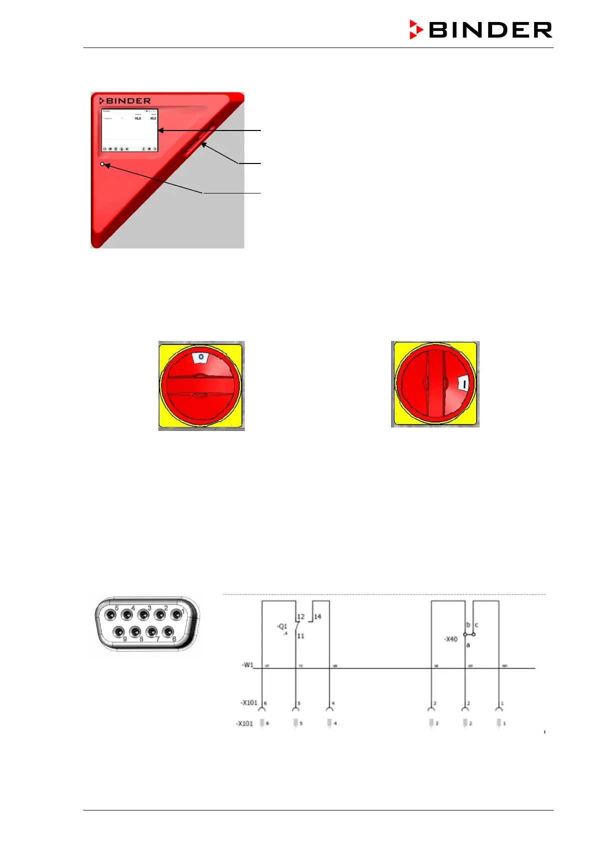
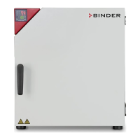
2.4 Main power switch (sizes 260 and 720)
The chambers sizes 260 and 720 are equipped with a main power (11) switch located on the chamber rear.
Off On
Figure 8: Main power switch (11) on the M 260 and 720 chamber rear
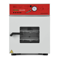
2.5 Zero-voltage switching contact
The chambers are regularly equipped with a zero-voltage switching contact.
The SUB-D socket “
ALARM / SWITCH CONTACT” (6) serves not only for collective alarm output via zero-voltage
alarm contact (chap. 13.3) but also for controlling a switching contact via the program controller, which
serve to switch any device connected to the zero-voltage relay output. They are controlled in the "Functions
on/off" menu of the chamber controller (chap. 8.4, 10.7.3, 11.6.5).
Switching contact 1
PIN 6 / PIN 5 / PIN 4
Switching contact 2
PIN 3 / PIN 2 / PIN 1
Figure 9: Pin allocation of the SUB-D socket „ALARM / SWITCH CONTACT“ (6)
for zero-voltage switching contact