M (E3.1) 1/2023 page 75/136
13.3 Zero-voltage relay alarm contact
Collective alarm output via the zero-voltage relay alarm contact
The chamber is equipped at the rear with a zero-voltage relay contact (6), which permits the transmission
of alarms generated by the chamber to an external monitoring system in order to monitor and record the
alarm signals.
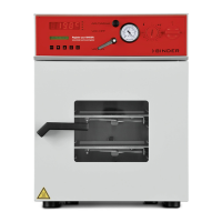
The connection is realized as 9-poles SUB-D socket “
ALARM / SWITCH CONTACT” (6) as follows.
PIN 8 = NO
PIN 9 = NC
Figure 13: Pin configuration of the SUB-D socket “ALARM / SWITCH CONTACT” (6) for zero-voltage relay alarm
contact
The zero-voltage relay alarm output switches immediately, as soon as the “Collective alarm” icon lights up.
The zero-voltage relay alarm output switches for all alarm instances and in case of a power failure.
If the external alarm monitor is connected via the contacts C and NO, alarm monitoring will take place with
protection against short-circuiting, i.e., if the connection between the chamber and the external alarm mon-
itor is interrupted, an alarm is triggered. In this case, power failure will also trigger the alarm.
When the chamber is running and there is no alarm, contact C closes with contact NO.
When the chamber is turned off or if there is an active alarm, contact C closes with contact NC.
Maximum loading capacity of the switching contacts: 24V AC/DC – 2.0 Amp.
DANGER
Electrical hazard through overload of switching contacts.
Deadly electric shock, damage to switching contacts and connection socket.
∅ Do NOT exceed the maximum switching load of 24V AC/DC – 2.0 Amp.
∅ Do NOT connect any devices with a higher loading capacity.
The alarm message on the controller display remains displayed during transmission of an alarm via the
zero-voltage relay outputs. As soon as the cause of the alarm is rectified, or the alarm message has been
reset, the alarm transmission via the zero-voltage relay outputs is reset together with the alarm message
on the controller display.
In case of power failure, transmission of the alarm via zero-voltage relay outputs remains active for the
duration of the power failure. Afterwards, the contact closes automatically.
Connection to an external monitoring system
To ensure short-circuit-proof alarm monitoring that will trigger the alarm when connected to an external
alarm monitor, connect the external alarm monitoring system to the chamber via the connection socket (6)
of the zero-voltage relay output.