Operating Instructions ACTIVE 06/07198
198 Operating Instructions ACTIVE 06/07
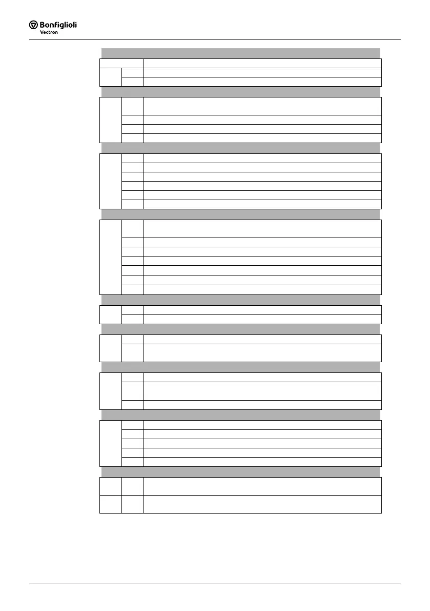
Inside
Code Meaning
00 Inside temperature too high, check cooling and fan.
F03
01 Inside temperature too low, check electrical cabinet heating.
Motor Connection
00
Motor temperature too high or sensor defective, check connection
S6IND.
01 Motor circuit breaker tripped, check drive.
02 V-belt monitoring reports no load on the drive.
F04
03 Phase failure, check motor and wiring.
Output current
00 Overloaded, check load situation and ramps.
03 Short circuit or earth fault, check motor and wiring.
04 Overloaded, check load situation and current value limit controller.
05 Asymmetric motor current, check current and wiring.
06 Motor phase current too high, check motor and wiring.
F05
07 Message from phase monitoring, check motor and wiring.
DC link voltage
00
DC link voltage too high, check deceleration ramps and connected brake
resistor.
01 DC link voltage too low, check mains voltage.
02 Power failure, check mains voltage and circuit.
03 Phase failure, check mains fuses and circuit.
04
Reference DC-Link Limitation 680 too low, check mains voltage.
05
Brake chopper
Trigger Threshold 506 too low, check mains voltage.
F07
06
Motor chopper
Trigger Threshold 507 too low, check mains voltage.
Electronics voltage
01 Electronics voltage 24 V too low, check control terminal.
F08
04 Electronics voltage too high, check wiring of control terminals.
Output frequency
00 Output frequency too high, check control signals and settings.
F11
01
Max. frequency reached by control, check deceleration ramps and con-
nected brake resistor.
Motor Connection
00 Earth fault on output, check motor and wiring.
01
Set
IDC-Compensation Limit 415 reached, check motor and cabling,
increase limit, if necessary.
F13
10 Minimum current monitoring, check motor and wiring.
Control Connection
01 Reference value on multifunctional input 1 faulty, check signal.
07 Overcurrent on multifunctional input 1, check signal.
30 Speed sensor signal defective, check connections S4IND and S5IND.
31 One track of the speed sensor signal is missing, check connections.
F14
32 Direction of rotation of speed sensor wrong, check connections.
Optional Components
F0A 10
Data transmission from control unit KP 500 to inverter failed. In the
control unit must be stored at least 1 file.
F0B 13
The communication module was fitted to slot B without disconnection of
the mains voltage, switch mains voltage off.
In addition to fault messages mentioned, there are further fault messages. However
these messages are only used for internal purposes and are not listed here. If you
receive fault messages which are not listed here, please contact us by phone.

 Loading...


