DiBos/DiBos Micro Connections | en 131
Bosch Sicherheitssysteme GmbH Installation Guide F.01U.033.308 | V7 | 2009.09
Variant 2:
The customer-operated ATMs are further away from the video system. The video system and
interface processor, as well as the interface processor and the ATMs, cannot be connected
together in such a way that the distance between each of them is less than 15 m. The ATMs
are, however, close enough together to allow them all to be connected to the interface
processor in such a way that the distance between the interface processor and each ATM is
less than 15 m.
Possible solution:
Connection of each ATM is made directly at the interface processor and is ATM-specific. To
increase the range, two OVS are required between the video system and the interface
processor.
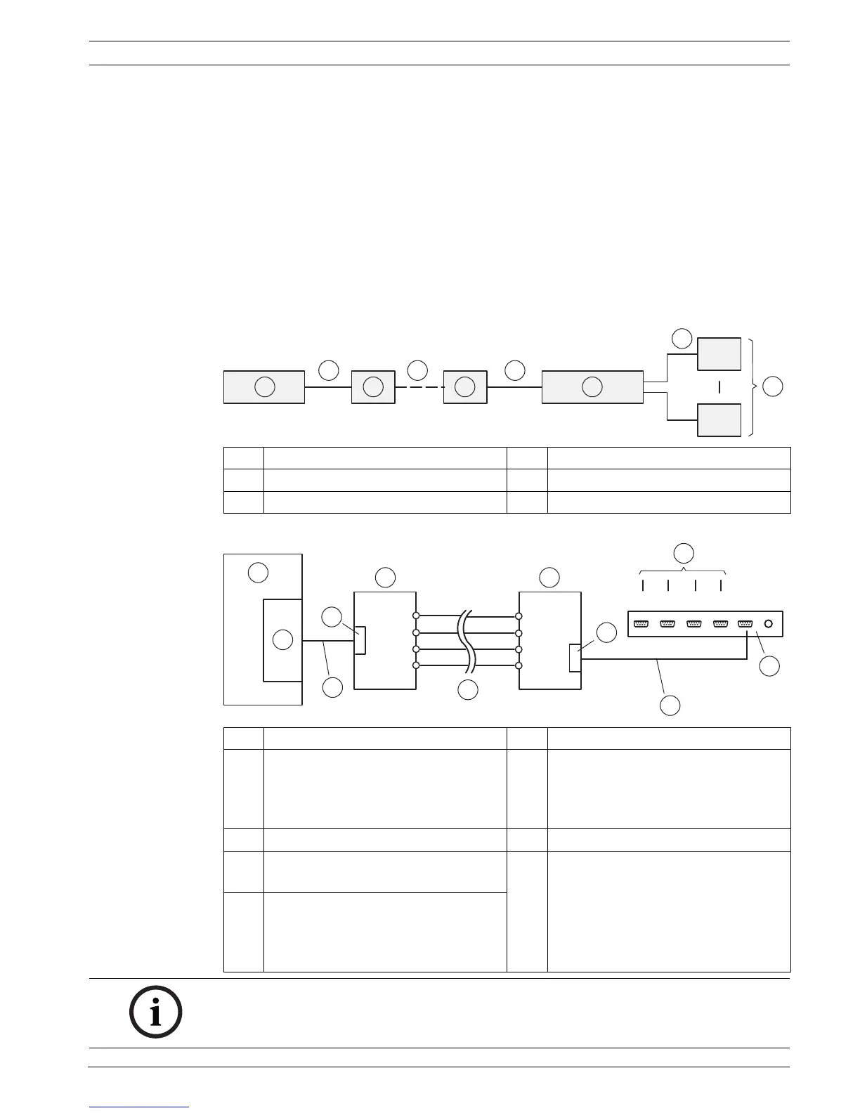
Connection principle:
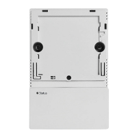
Connection details:
1 Video system 4 Max. 1000 m
2 Max. 15 m 5 Interface processor
3OVS 6ATM1 - ATM4
1 Video system 6 Max. 1000 m
2 COM x 7 OVS 2
BR1 and BR2: Position 2/3
ST3: Pin 2 = receive line, Pin 3 =
transmit line
39-pin 8Interface processor
4 Connection cable, 9-pin, part no.
4.998.079.686 (1:1 connection)
9 To ATM1 - ATM4
5OVS 1
BR1 and BR2: Position 1/2
ST3: Pin 2 = transmit line, Pin 3 =
receive line