20
Panel Descriptions
fig.panel-L.eps
1.
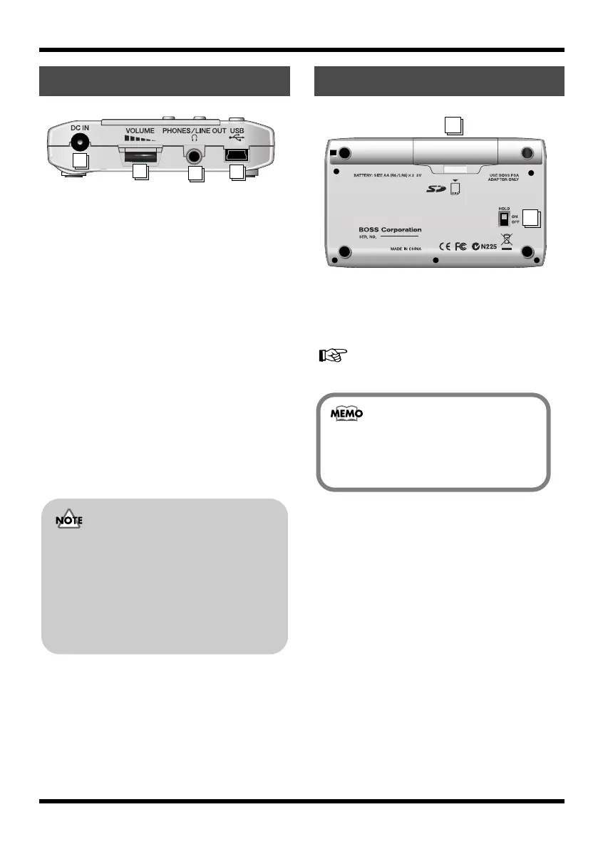
DC IN (AC Adaptor) Jack
An AC adaptor (PSA series, sold separately)
can be connected here (p. 23). You can
purchase a PSA series from your musical
instrument dealer.
2.
VOLUME
Adjusts the volume of the output from
PHONES/LINE OUT.
3.
PHONES/LINE OUT Jack
This is an output jack for connecting stereo
headphones (sold separately) or external
audio equipment (e.g., stereo amp).
4.
USB Connector (MINI B type)
Use this connector to connect the MICRO BR
to your computer via a USB cable. This
allows data to be transferred between the
MICRO BR and your computer (p. 23), (p.
102).
fig.bottom-panel.eps
1.
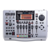
Battery Cover
Here you can insert batteries and a memory
card (SD memory card). You can’t record if
no memory card is inserted.
“Inserting batteries and a memory card” (p. 21)
2.
HOLD Switch
While the power is on, you can turn the
HOLD switch ON to disable the operation of
all buttons. However, even if HOLD is ON,
you will still be able to adjust VOLUME and
INPUT LEVEL.
If you turn the HOLD switch ON while the
power is off, pressing the [POWER] will no
longer turn on the power.
Side panel (left)
2
3
4
1
• You must use only the PSA series as
the AC adaptor. Using any other
adaptor may cause malfunctions or
damaged.
• Your data may be lost if you
disconnect the AC adaptor during
operation.
Bottom panel
1
2
When the MICRO BR is shipped from the
factory, a SD card containing a demo
song is installed.
MICRO-BR_e.book 20 ページ 2009年5月28日 木曜日 午後2時26分