142
HYPERION User Manual Bruker Optik GmbH
Repair and Maintenance 6
6.4.5 Aligning the ATR crystal centrically
General information
For aligning the ATR crystal in horizontal direction, the three slotted-head screws at the
inner ring at the ATR objective bottom side have to be tightened only loosely, not firmly.
(See section 6.4.3, step 9 of the crystal assembly replacement procedure.)
Correct the horizontal alignment of the crystal with the ATR objective being attached at
the revolving nosepiece and being placed in the beam path.
Required tools
• hex wrench (Note: This hex wrench is included in the delivery scope of the ATR
crystal.)
Procedure
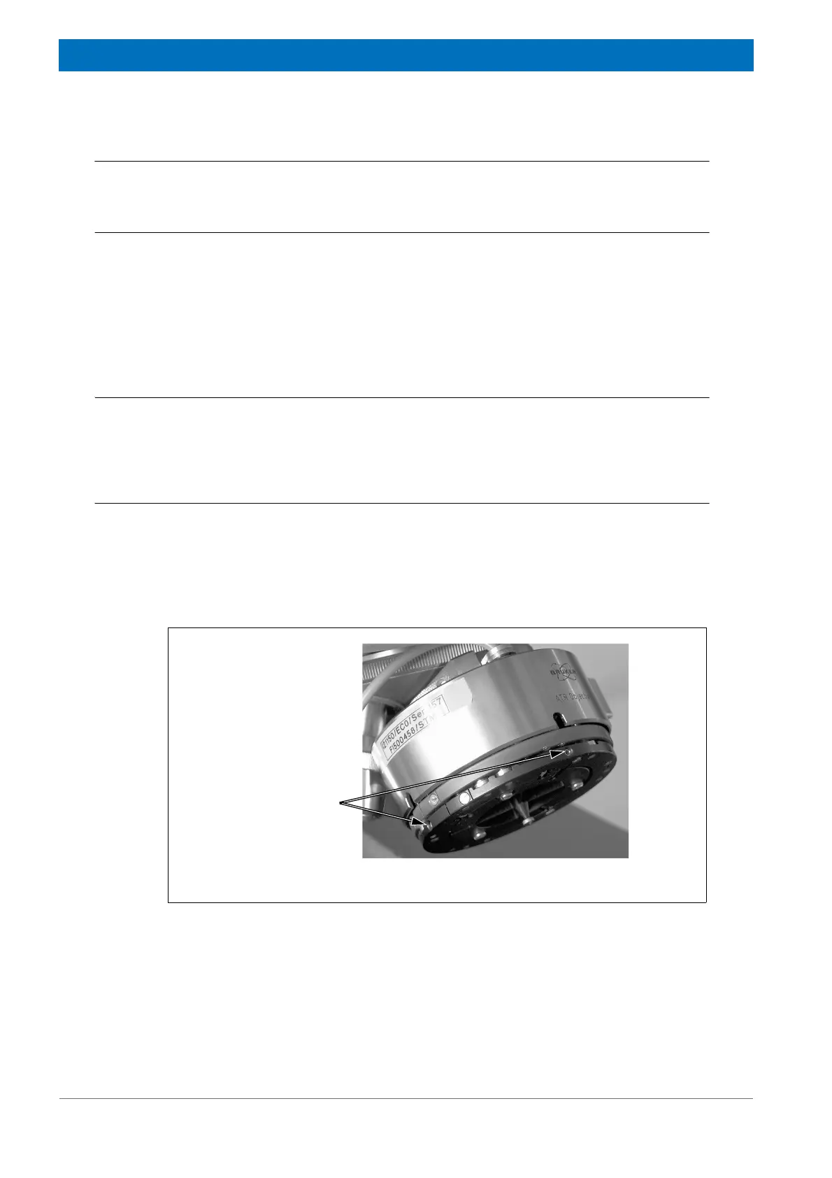
1. Adjust the crystal position in the horizontal plane by rotating the adjusting screws
(fig. 6.7) using the hex wrench. In doing so, the crystal assembly is moved in the
corresponding direction in horizontal plane. The direction in which the crystal
assembly needs to be moved depends on the position of the crystal tip imprint in
relation to crosshairs center. (An example is shown in fig. 6.6b.)
2. Recheck the ATR crystal position for centrality. (See section 6.4.4.)
3. If the check reveals that the ATR crystal is in the center position, tighten firmly the
three slotted-head screws at the inner ring at the ATR objective bottom side
(fig. 6.8). Otherwise, repeat step 1 and step 2 above. When tightening firmly the
three slotted-head screws at the ATR objective bottom side, be careful not to dis-
place the crystal assembly again!
Figure 6.7: Aligning the ATR crystal centrically
Screws for adjusting
the crystal assembly
in horizontal direction