Section4:Adjustments 4-15
Ball Detect Adjustments
WARNING: Before adjusting the ball detector, turn the stop/run switches on
the pinsetter to the stop position. Failure to do this may result in personal
injury caused by pinsetter cycling when the ball detect’s beam is interrupted
or the pinsetter is turned on at the Control Desk.
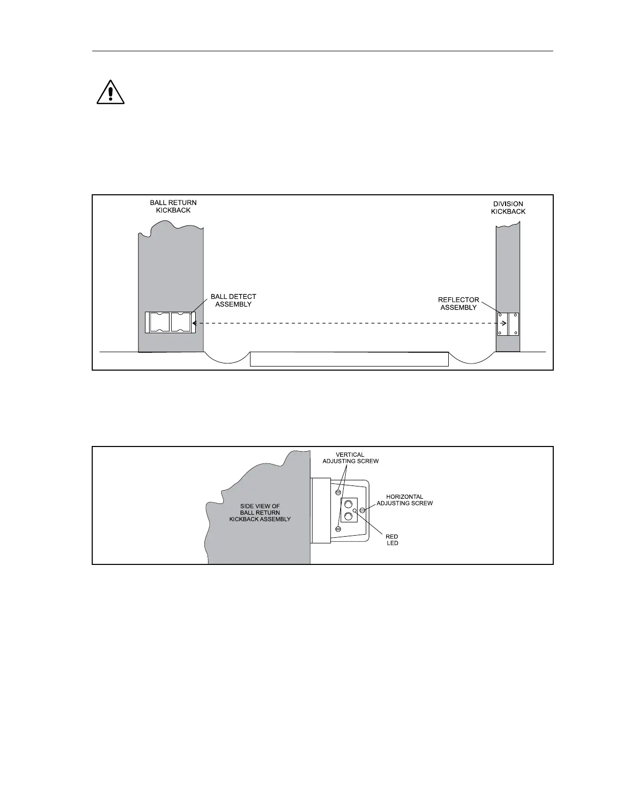
The ball detect adjustment contains three screws that are used to align the units infrared beam with a
reector opposite side of the lane. Refer to Figure4-14.
Figure4-14.BallDetectandReector
The red LED (Light Emitting Diode) mounted on the ball detect is “on” when the beam is not being
received back from the reector. This indicates a ball or some object is in the beam’s path or there is an
alignment problem. Refer to Figure4-15.
Figure4-15.BallDetectAdjusting
1. Check the face of the ball detect and make sure it is parallel with the face of the ball detect’s
housing. Check the reector to see if it is mounted securely and parallel to the ball detect.
Clean the transmitter, receiver and reector before and after adjusting.
2. Cover the reector with a dark non-reective object. The red LED should be lit indicating the
beam is not being received.
3. Hold an unmounted reector in your hand and move it above, below and around the mounted
reector until the red LED goes “o.” This will indicate the position of the beam and guide you
in your adjustment.
4. Using the vertical and horizontal adjusting screws (refer to Figure 4-15) move the beam until it
is aimed exactly on the center of the mounted reector.